00197902-03_UM_X-Serie-S_EN.pdf - 第234页
4 Setting up and commissioning User manual SIPLACE X-Series 4.3 Setting up the machine From softwa re version 710.0 Edition 12/2016 234 4 4 4 Carefully loosen both hexagon so cket-head screws M24x90 ( item 2 in fig. 4.…
User manual SIPLACE X-Series 4 Setting up and commissioning
From software version 710.0 Edition 12/2016 4.3 Setting up the machine
233
Screw the thread of the middle machine foot into the hole provided on the underside of the
spacer.
Align both spacers as follows:
– The spacer opening on the pneumatic unit side points in the direction of board conveyor
travel (see item 4 in fig. 4.3 - 4
, page 230).
– The spacer opening on the power supply side points in the opposite direction to that of
conveyor travel (see item 3 in fig. 4.3 - 4
, page 230).
Fasten each of the two spacers with four hexagon socket-head screws M12x80 (see item 4
in fig. 4.3 - 6
). Use the screwdriver bit of size 10 mm.
4.3.6.2 Presetting the height of the outer machine feet
4
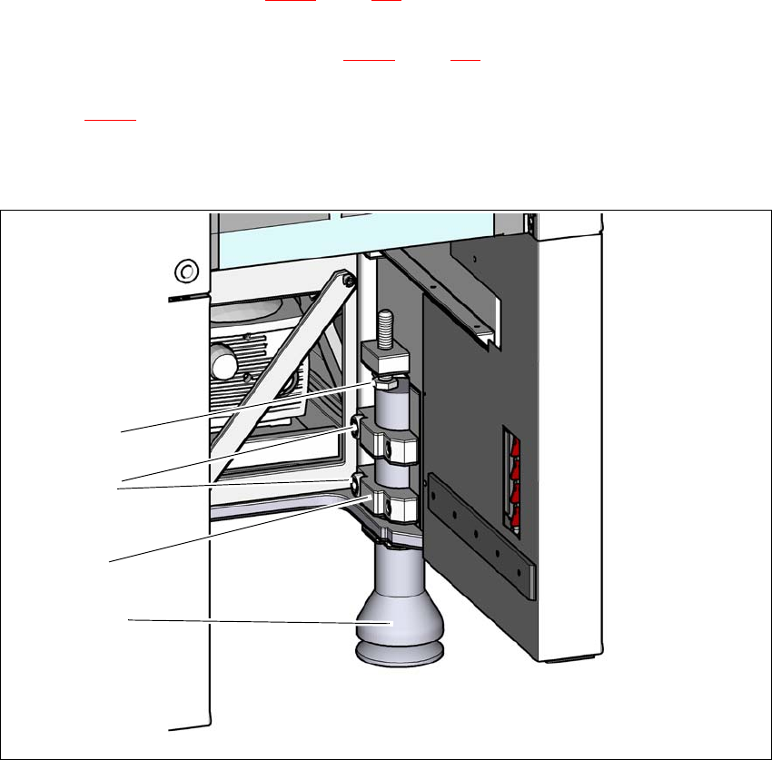
Fig. 4.3 - 7 Presetting the height of the outer machine feet
(1) Setting screw M24x2x120 for height adjustment
(2) Outer machine foot
(3) Clamping piece
(4) Hexagon socket-head screw M24x90
(4)
(2)
(1)
(3)
4 Setting up and commissioning User manual SIPLACE X-Series
4.3 Setting up the machine From software version 710.0 Edition 12/2016
234
4
4
4
Carefully loosen both hexagon socket-head screws M24x90 (item 2 in fig. 4.3 - 7, page 233)
with the screwdriver bit (size 19 mm) and let the outer machine foot (item 1 in fig. 4.3 - 7
, page
233
) slowly slide down as far as the end stop.
Insert the correct machine foot for the required PCB conveyor height.
– Outer machine feet for the PCB conveyor heights 900,930 and 950 mm, length
439 mm, Item no. 03000890-02 (item 1 in fig. 4.3 - 4
, page 230 )
Perform this presetting for each of the outer machine feet.
The distance between the machine foot underside and the lower edge of the machine frame
should be as follows:
Adjust the setting screw M24x2x120 (item 3 in fig. 4.3 - 7, page 233) with the fork wrench SW
36, so that you achieve the distance values for the relevant conveyor height, as specified in
the table above.
CAUTION
Risk of cuts at the used tape chute!
When you turn the setting screw M24x2x120 to adjust the height (item 1 in fig. 4.3 - 7
,
Semite233
) there is a risk of cutting yourself on the sharp edges of the used tape chute.
Always wear thick safety gloves.
WARNING
Heavy machine part
The machine feet are very heavy. When loosening individual screws, these could fall
down and crush limbs.
When replacing the machine feet, raise the machine slightly.
Make sure that no-one is in the hazard area. Risk of crushing due to unintentional
movement or lowering of machine.
WARNING
Do not move machine!
The conveyor sides could be damaged.
Make sure that the machine is not moved and that the conveyor sides are not dam-
aged.
PCB conveyor height Distance of machine foot underside to lower edge of
machine frame
900 mm 190 mm
930 mm 220 mm
950 mm 240 mm

User manual SIPLACE X-Series 4 Setting up and commissioning
From software version 710.0 Edition 12/2016 4.3 Setting up the machine
235
Now use the fork-lift to carefully lower the machine until the machine feet touch the floor
evenly. There should always be a second person present to ensure that the machine remains
stable while it is being lowered. You may need to loosen the outer machine feet clamp slightly.
Continue to carefully lower the machine, until the outer machine feet touch the height adjust-
ment setting screws M24x2x120 (item 3 in fig. 4.3 - 7
, page 233).
Make sure that the middle machine feet (see item 2 in fig. 4.3 - 4, page 230) do not yet touch
the ground. If necessary, screw the middle machine feet back into the machine or spacer a
little.
4
PLEASE NOTE
For a description of how to perform final adjustment on the machine, refer to the section
4.3.8.1
, page 238.