00197902-03_UM_X-Serie-S_EN.pdf - 第345页
User manual SIPLACE X-Series 6 Station extensions From software version 710.0 Ed ition 12/2016 6.1 Nozzle changer 345 6.1.5.3 Configuration example: T winSt ar for SIPLACE X4 S One nozzle changer can be installe d at eac…

6 Station extensions User manual SIPLACE X-Series
6.1 Nozzle changer From software version 710.0 Edition 12/2016
344
6.1.5.2 Technical data
6
Nozzle changer for the SIPLACE TwinStar
Number of magazines
Locations 1 and 3 6
Locations 2 and 4 6
max. 12 magazines for max. 24 nozzle garages
max. 10 magazines for max. 20 nozzle garages
Number of nozzle holders may be freely configured
Standard configuration 3 magazines with two nozzle garages each
1 magazine with one nozzle garage
Nozzle types 4 xx with adapter
5xx (standard)
9 xx with adapter
Special nozzle, gripper
User manual SIPLACE X-Series 6 Station extensions
From software version 710.0 Edition 12/2016 6.1 Nozzle changer
345
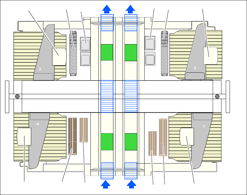
6.1.5.3 Configuration example: TwinStar for SIPLACE X4 S
One nozzle changer can be installed at each of the following locations for the TwinStar.
Nozzle changer at location 1, 3 and 4: 12 magazines
Nozzle changer at location 2: 10 magazines
This gives a total capacity of 2 nozzle changers with 22 magazines and a total of 44 nozzle ga-
rages.
6
Fig. 6.1 - 25 Position of nozzle changer for the SIPLACE TwinStar machine - configuration example (SIPLACE X4 S)
(1) Nozzle changer for the TwinStar
(2) TwinStar
(3) Stationary cameras
(4) MultiStar
(5) Nozzle changer for the MultiStar
(6) Nozzle changer row 2 Multistar (optional)
(4)
(5)
(5)
(4)
(1)
(2) (2)
(3)
(3)
(1)
(6)
(6)
6 Station extensions User manual SIPLACE X-Series
6.1 Nozzle changer From software version 710.0 Edition 12/2016
346
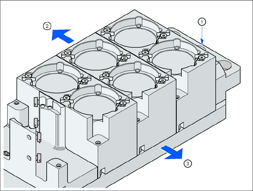
6.1.5.4 Assembly
The nozzle changer is fixed to the component trolley COT insert.
6
Fig. 6.1 - 26 Assembly position
(1) Marking hole
(2) Operator side
(3) Arrow pointing toward the PCB conveyor
6
Align the nozzle changer so that the marking hole (item 1) is on the left, as viewed by the op-
erator.