RV-2-3D_SPE_EN - 第6页
RV - 2 PRODUCT SPECIFICA T IONS 3 4. Applicable Boards A pplicable board specification Item Spe cification Externa l board dimens ions Single m ode S tandard s pec ificatio ns : 50 (W ) x 50 (D ) to 410 (W ) x 300 (D) …
RV-2 PRODUCT SPECIFICATIONS
2
2. Basic Specification
Item
Specification
Model name RV-2-3D
External dimensions
940 (W) x 1,276 (D) x 1530 (H) mm
(2,056 (H) mm signal tower included)
Weight 1,000 kg
Electric power
3-phase AC200 to 230 V 50/60 Hz 2.0 kVA or less
* Connection specification
Power supply cable: 2.0 mm
2
x 4-core cable, less than 3 m
Terminal block size: Terminal screw(M4), compatible power cable
AWG10-14 (2-5.5sq)
Terminal shape: Round terminal with insulation Terminal size 5.5 mm,
compatible screw diameter 4 mm
Air supply pressure
0.49 MPa
* Connection specification
Hose connection shape: Hi Cupla 20PM (Nitto Kohki)
Reference international standards for machine safety
Machinery Directive EN ISO 12100:2010, EN 60204-1:2006+A1:2009, 2006/42/EC ANNEX I
3. Environment Condition
Transportation and storage conditions
Item
Environment condition
Transportation and
storage temperature
+10~+60℃
Transportation and
storage humidity
30% to 80% (with no condensation)
Operating environment condition
Item
Environment condition
Ambient temperature
+15~+30℃
Ambient humidity 30% to 65% (with no condensation)
Altitude 1000 m or less from the sea level
Degree of pollution
2 (IEC60664-1 compliant, corresponding to general electronic circuit board
assembly lines)
Overvoltage category III (IEC60664-1 compliant)
RV-2 PRODUCT SPECIFICATIONS
3
4. Applicable Boards
Applicable board specification
Item
Specification
External board dimensions Single mode
Standard specifications:
50 (W) x 50 (D) to 410 (W) x 300(D) mm
long size specification:
50(W)
×
50(D)
~
630(W)
×
300(D) mm
Board thickness 0.3 to 8.0 mm
Maximum board height
Standard Top side: 40 mm Bottom side: 70 mm
* 20 to 60 mm can be accommodated as the height on the top side by
changing the height of lighting.
(Selectable at the time of purchase)
Payload
4.0 kg or less (The transfer speed is changed variably according to the
payload.)
* Please consult us if the weight exceeds the limit.
∗ The maximum board dimensions need to be changed according to the board weight and shape.
Loading a board having a part whose height exceeds 40 mm on the top side or 70 mm on the bottom side
may damage the board or cause the device to malfunction. (The above dimensions provide clearances
from the lights when boards are transferred and inspected.)
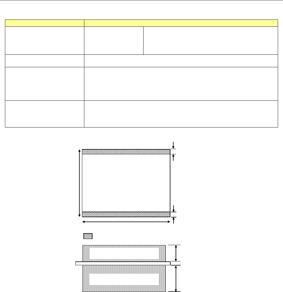
Board fixture part of inspection
• Single mode
3 mm
50 to
360 mm
50 to 410 mm
3 mm
PWB
PWB thickness:
0.3 to 8.0 mm
40 mm
* 20 to 60 mm can be accommodated by changing
70 mm
Clearance above board
Clearance below board
RV-2 PRODUCT SPECIFICATIONS
4
5. Inspection Function Specification
Item
Specification
Types of boards that can be
inspected
After solder printing, before reflow, after reflow
Parts that can be inspected
Parts gap 0.3 mm or more, square chips of 0603 or more, cylindrical
chips,
tantalum capacitors, aluminum chip capacitors, transistors,
SOP/QFP (0.3 mm or greater pitch), connectors,
leads of discrete parts
* When selecting the optional lens of 10μm/pixel
Parts gap 0.2 mm or more, square chips of 0402 or more
Inspection item
Lack of parts, offset, polarity, front-side back, no solder, bridge, solder
amount, Part's height, lead floating
disconnected insertion part, etc.
* Optional: Character-recognition (OCR/OCV), code reader (1D, 2D)
6. Hardware Specification
Item
Specification
Image processing system
Color image processing
• 400-million-pixel CMOS color camera
• Image processing library HALCON11
• High-brightness white LED 3-stage lighting + coaxial illumination
Resolution Standard: 15.0 μm/pixel Optional lens: 10.0 μm/pixel
Image range Standard: 30.0 x 30.0 mm Optional lens: 20.0 x 20.0 mm
Transfer conveyor type Single track
Transfer conveyor width
adjustment
Automatic adjustment
Height of transfer
conveyor
900 mm -20 mm to +70 mm Adjustable using the adjuster feet
Processing time 0.41 second/ 1 screen (In the maker optimum)
Positioning Reference on end face of board
Control computer OS Windows 7, 64-bit
External code reader
Communication IF: RS-232C
* Please contact us for the recommended equipment.
Network 100 Mbps Ethernet or faster (1 Gbps Ethernet recommended)