00194422-09_MM_X-Series_en.pdf - 第11页
Introduction 1.1.9 Laser Classification Safety Instructions Maintenance Manual SIPLACE X Series 11 1.1.9 1 . 1 . 9 L a s e r C la s s if ic a t io n Laser Classification 1.1.9.1 1 . 1 . 9 . 1 L a s e r C la s s 1 Laser C…
Introduction
Safety Instructions 1.1.8 Safety Instructions on Hazardous Materials
10 Maintenance Manual SIPLACE X Series
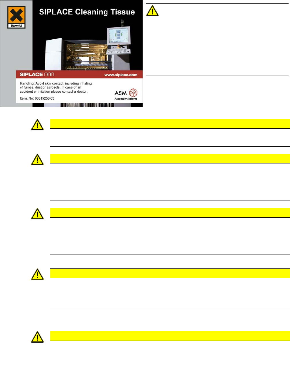
SIPLACE cleaning tissue
Consumables
Cleaning and lubri cation
Danger of c utting on the IC and FC camera
Only one person must be present at each component preparation station at any given time
1.1.8
1.1.8 Safety Instructions on Hazardous Materials
Safety Instructions on Hazardous Materials
CAUTION!
SIPLACE cleaning tissue
Harmful: may cause lung damage if swallowed.
Do not inhale vapor / aerosol.
Avoid contact with the skin. If swallowed, do not induce
vomiting. See medical attention immediately and show
the packaging or label.
Wear latex gloves while using the cleaning tissue.
CAUTION
Consumables
Observe the safety data sheets for consumable materials!
CAUTION
Cleaning and lubrication
► Always use ethanol for cleaning – do not use solvents.
► Isopropanol – IPA can be used as an alternative.
► NEVER use compressed air to clean units inside the placement machine or modules.
CAUTION
Danger of cutting on the IC and FC camera
There is a risk of cutting your fingers along the edges of the mirror.
► Wear laboratory gloves as protection and avoid touching the edges.
► The laboratory gloves are also required for effective cleaning (fingerprints!).
CAUTION
Only one person must be present at each component preparation station at any given time.
This is to ensure the safety of the operator and the safety of the second person. Pulling in the
component trolley is a two-handed operation, so only one person can be reliably protected from
the possible risks.
CAUTION
Observe the safety data sheets
Observe the applicable safety data sheet, when handling hazardous materials (e. g. Loctite
241, ethanol).
Introduction
1.1.9 Laser Classification Safety Instructions
Maintenance Manual SIPLACE X Series 11
1.1.9
1.1.9 Laser Classification
Laser Classification
1.1.9.1
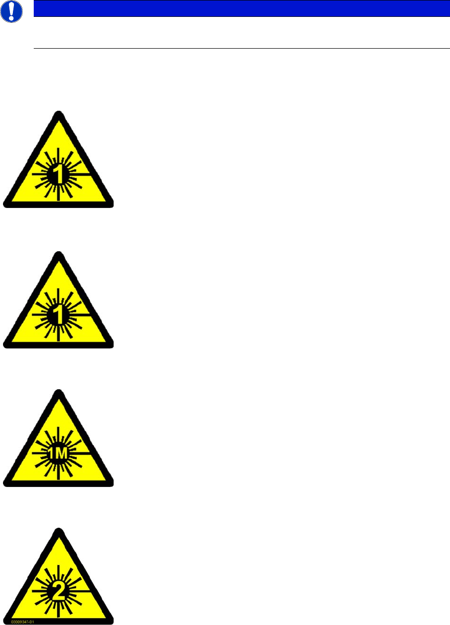
1.1.9.1 Laser Class 1
Laser Class 1
Classification of the Whole Machine
Classification of the Camera Systems
1.1.9.2
1.1.9.2 Laser Class 1M
Laser Class 1M
1.1.9.3
1.1.9.3 Laser class 2
Laser class 2
NOTICE
Laser class 1 and 1M
Modules in laser classes 1 and 1M are not labeled.
All installed camera systems and the whole machine (when ready for oper
-
ation) are assigned to laser class 1.
The laser classes are determined according to DIN EN 60825-1:2001.
The following camera systems are assigned to laser class 1:
▪ Stationary component cameras for the SIPLACE TwinStar (TwinHead)
and the SIPLACE Multistar (CPP)
▪ Component camera, stationary, P&P, type 33, 55 x 45, digital
▪ Component camera, stationary, P&P, type 25, 16 x 16, digital
▪ Component camera, stationary, P&P, type 36, 32 x 32, digital
Do not look directly at this with optical instruments!
The following camera systems are assigned to laser class 1M:
▪ CO camera C&P, type 23, 6 x 6 on the SpeedStar
▪ CO camera C&P, type 41, 6 x 6 on the SpeedStar
▪ CO camera C&P, type 30, 27 x 27 on the MultiStar
▪ CO camera C&P, type 30, 18 x 18 on the 12-segment Collect&Place
head
Laser radiation
Do not look into beam!
The following modules are assigned to laser class 2:
▪ PCB barcode scanner
▪ Component sensor on the SpeedStar
▪ Component sensor on the MultiStar
The entire machine is classified as laser class 2 if the coplanarity laser mod
-
ule option is installed.
Introduction
Preparatory Work... 1.1.9 Laser Classification
12 Maintenance Manual SIPLACE X Series
1.2
1.2 Preparatory Work...
Preparatory Work...
Purpose and Scope
Before performing any preventive maintenance work, conversion work or service work, a procedure of
locking and tagging must be followed and warning signs must be attached if not stated otherwise. If it is
not necessary to switch off the machine, it is explicitly mentioned.
The procedure, when followed correctly, eliminates the possibility of an employee being injured.
Description
Whenever it becomes necessary to isolate, control and release energy, the following procedure is to be
followed.
► Notify affected employees.
► Switch off the machine and all additional devices. Carry out all normal stopping procedures:
⇨ Press the STOP button.
⇨ Shut down the station computer.
⇨ Switch the machine off at the main switch.
► Isolate the machine from all its energy sources:
⇨ Shut off the compressed air supply.
⇨ Shut off the main power supply.
► Lock out the machine.
⇨ Attach a lock wherever possible (e.g. to the main power switch or the motor contactor).
► Alternative: attaching warning signs
If a machine can be locked, it must be. However, there are situations where energy isolating devices
cannot accommodate locks. In these cases, the energy isolating devices must be tagged to warn
employees that the machine is de-energized for servicing. The tag or label must be securely fas
-
tened, it must be placed in a position visible to all and it may only be removed by the person who
attached it.
NOTICE
Additional safety measures
These procedures represent the minimum lock/tag out requirements for the machine during
preventive maintenance work and service work. Any additional safeguards needed to complete
work safely can be specified by facilities supervision, the safety officer, the safety committee
and the health department.
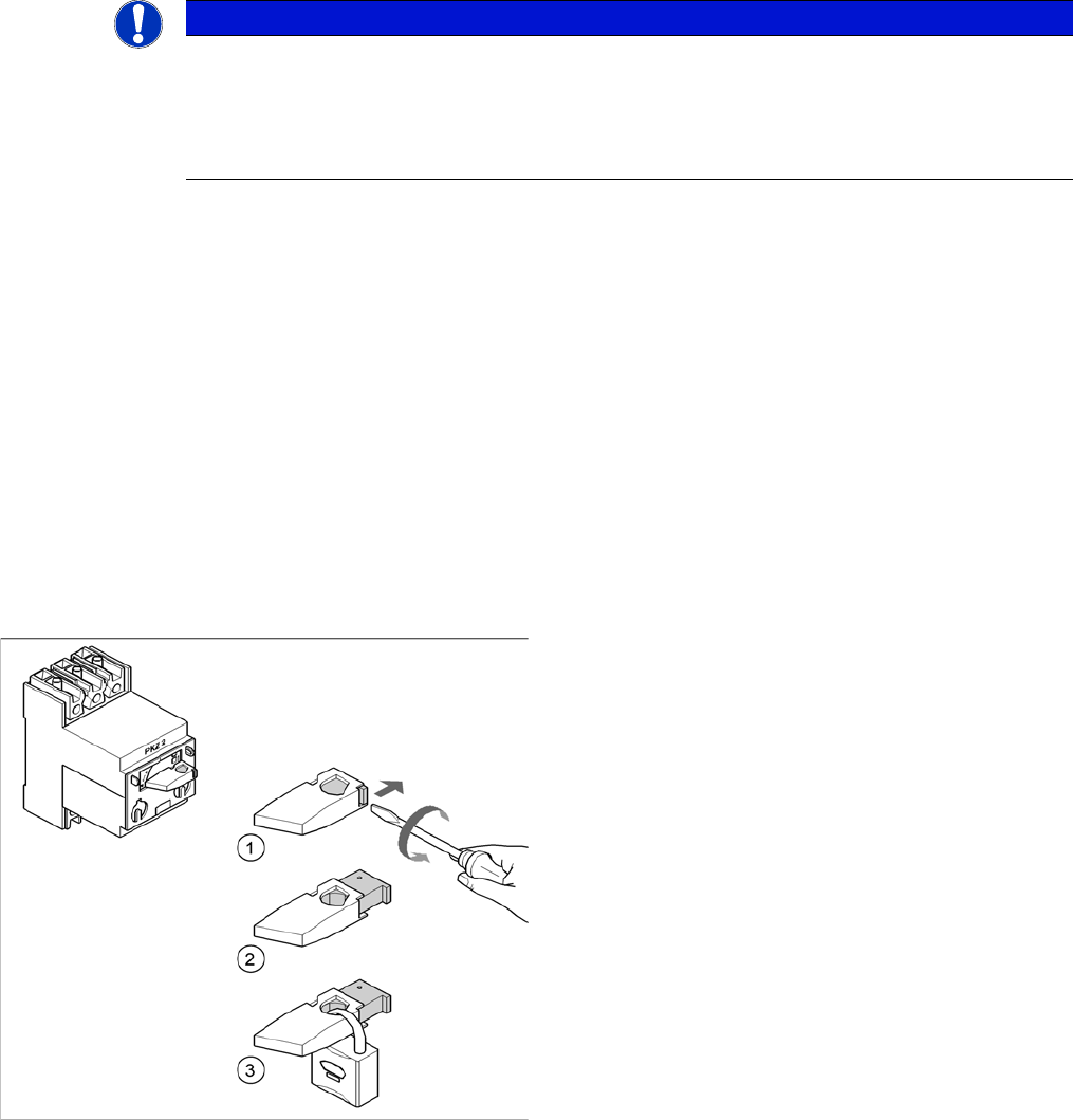
Example: attaching a padlock to the motor contactor
► Turn the operating lever (1) counterclockwise.
► Use the screwdriver to push the locking lug (2) out of
the operating lever (1).
► Secure the operating lever with a padlock (3).