00194422-09_MM_X-Series_en.pdf - 第33页
Major Maintenance 5.2.1 Tools, Consumables, Spare and Wear Parts Maintenance Tasks for Base Machine Maintenance Manual SIPLACE X Series 33 5.2 5 . 2 M a in t e n a n c e T a s k s f o r B a s e M a c h in e Maintenance T…

Major Maintenance
Maintenance Intervals for Major Maintenance
32 Maintenance Manual SIPLACE X Series
2225 - Major - Optical Systems - X-Series
2325 - Major - Gantry - X-Series
9000 – Foot not e * Maintenanc e display
* see also maintenance display
2425 - Major - Conveyor - X-Series
See also
1.3.2 Calculation of Maintenance Intervals [ ➙ 15]
Maintenance tasks
Optical systems
Duration
[min]
Each
week
Every 3
months
Every 6
months
Every 12
months
Cleaning the IC and FC Cameras 4 X
Clean the coplanarity module 2 X
Cleaning the Stationary 3D Sensor Module 2 X
Cleaning the PCB Barcode Scanner 2 X
Maintenance tasks
Gantry
Duration
[min]
Each
week
Every 3
months
Every 6
months
Every 12
months
Greasing and Cleaning the Guide Bearing of the X
Axis
2X
Greasing and Cleaning the Guide Bearing of the Y
Axis
2X
Cleaning the Linear Guides of the X Axis 2 X
Cleaning the Linear Guides of the Y Axis 2 X
Cleaning the X Axis Scale 2 X
Cleaning the Y Axis Scale 2 X
Checking the Cooling Air Hoses for the Y Axis 2 X
Maintenance tasks
Conveyor
Duration
[min]
Each
week
Every 3
months
Every 6
months
Every 12
months
Adjust the conveyor sides for DC/QC 2/3 X
Cleaning and Preserving the Conveyor
▪ Hexagonal shafts
▪ Fixing strip
▪ Recirculating spindle
▪ Guide shafts of the width adjustment
▪ Guide shafts of the conveyor sides
11 X
Major Maintenance
5.2.1 Tools, Consumables, Spare and Wear Parts Maintenance Tasks for Base Machine
Maintenance Manual SIPLACE X Series 33
5.2
5.2 Maintenance Tasks for Base Machine
Maintenance Tasks for Base Machine
5.2.1
5.2.1 Tools, Consumables, Spare and Wear Parts
Tools, Consumables, Spare and Wear Parts
▪ Lint-free cloths [03082092-xx]
▪ SIPLACE cleaning cloth [00315253-xx]
▪ Protective latex gloves [00372972-xx]
▪ ESD wristband [00320279-xx]
▪ Set of Allen keys
▪ Axial fan type 4414 FNN (covers) [03056479-xx]
▪ Axis unit version 1 and 2 (center and bottom): axial fan 4414F 24 VDC [00319141-xx]
▪ Axis unit version 3 (center and bottom): axial fan air vent 24 VDC [03057927-xx]
▪ Fan unit for computer unit [03006602-xx] (not for BoxPC - the fan for the BoxPC is in the computer
and is monitored by this.)
▪ Filter element 40 µm (head exhaust air filter for X axis) [03003717-xx]
▪ Felt filter RFF-092-NV (axis and computer unit) [03006574-xx]
▪ Filter unit - plastic grate (axis and computer unit) [03003425-xx]
▪ O-Ring DIN3771 44.12 x 2.62 - NBR70 [03063579-xx]
▪ If required, gas pressure shock absorber 560 N (for cover above 2 gantries) [03036763-xx] or gas
pressure shock absorber 510 N (for cover above 1 gantry) [03039170
-
xx]
▪ Cooling air filter Y-axis (air filter unit for suction air filter) [00376006-xx], if required
▪ New compressed air filter, if required:
– Replacement filter for F74G-6GN-QP1 5 μm (compressed air filter for pneumatic valve)
X series version 1 up to B-089 / HF, version 1 up to A-229 [03038979-xx]
– Filter element 5 μm C.33-62 for [03038691-xx] (compressed air filter for pneumatic valve)
SX4 / X-Series S / X-Series version 2+3 / X4i / D3 (all) / HF version 2+3 [03039182-xx]
▪ If required, cover switch [03020409-xx]
▪ Weak or slightly alkaline cleaning agent, if required
5.2.2
5.2.2 Preparatory Steps
Preparatory Steps
► There must be no PCBs on the PCB conveyor for the following jobs.
See also
1.2 Preparatory Work... [ ➙ 12]
Major Maintenance
Maintenance Tasks for Base Machine 5.2.3 Performing Maintenance Tasks
34 Maintenance Manual SIPLACE X Series
5.2.3
5.2.3 Performing Maintenance Tasks
Performing Maintenance Tasks
5.2.3.1
5.2.3.1 Checking the Safety Features
Checking the Safety Features
Danger - No t functioning safety feature s
➢ Make sure that the placement system is switched on and the operating system has started up.
➢ Make sure that "Control on" is set on the placement machine. You can tell this from the main fault
indicator.
► Press the Start button.
Protective cover switch
► Check that the actuator moves cleanly and effortlessly into the switching unit. If this is not the case,
align the actuator and cover switch with respect to one another.
► Repeat these steps for all cover switches.
EMERGENCY STOP button
DANGER
Not functioning safety features
Not functioning safety features are dangerous.
► If any of the safety features does not function, switch off the machine immediately and se
-
cure the machine against unauthorized reactivation.
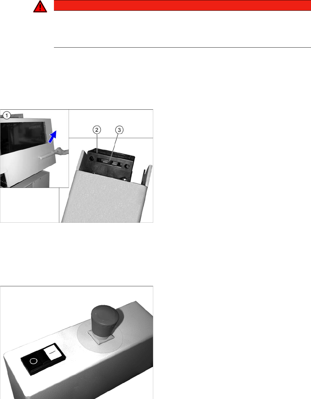
► Open the protective cover (1). The other protective
cover must be closed.
► The control must switch off immediately. You will hear
this clearly by the venting compressed air.
► Move the gantry in the X and Y directions. If the con
-
trol does not switch off or the gantry does not move
effortlessly, then the cover switch (2) may be defec
-
tive. In this case, replace the cover switch. For re
-
moval and installation details, read the service
manual for your machine.
► Check the hood switch for damage, particularly the
plastic web (3) in the middle. If there is any damage,
replace the cover switch with a new one. For removal
and installation details, read the service manual for
your machine.
► Check the EMERGENCY STOP buttons for damage.
► Check that the control system switches off immedi
-
ately when you actuate the button. If this is not the
case, have the button replaced by authorized person
-
nel.
► Repeat this procedure for all emergency stop but
-
tons.