00194422-09_MM_X-Series_en.pdf - 第35页
Major Maintenance 5.2.3 Performing Maintenance Ta sks Maintenance Tasks for Base Ma chine Maintenance Manual SIPLACE X Series 35 Monitoring the Reject Bin Conveyor - Mon itoring the No zzle Magazine s Monitoring the Nozz…
Major Maintenance
Maintenance Tasks for Base Machine 5.2.3 Performing Maintenance Tasks
34 Maintenance Manual SIPLACE X Series
5.2.3
5.2.3 Performing Maintenance Tasks
Performing Maintenance Tasks
5.2.3.1
5.2.3.1 Checking the Safety Features
Checking the Safety Features
Danger - No t functioning safety feature s
➢ Make sure that the placement system is switched on and the operating system has started up.
➢ Make sure that "Control on" is set on the placement machine. You can tell this from the main fault
indicator.
► Press the Start button.
Protective cover switch
► Check that the actuator moves cleanly and effortlessly into the switching unit. If this is not the case,
align the actuator and cover switch with respect to one another.
► Repeat these steps for all cover switches.
EMERGENCY STOP button
DANGER
Not functioning safety features
Not functioning safety features are dangerous.
► If any of the safety features does not function, switch off the machine immediately and se
-
cure the machine against unauthorized reactivation.
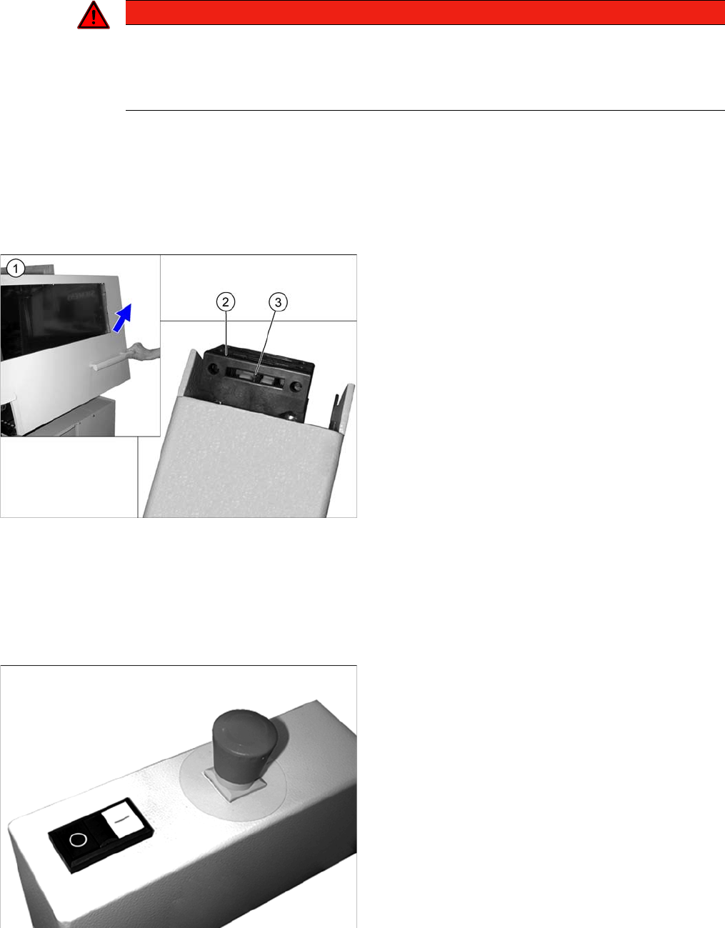
► Open the protective cover (1). The other protective
cover must be closed.
► The control must switch off immediately. You will hear
this clearly by the venting compressed air.
► Move the gantry in the X and Y directions. If the con
-
trol does not switch off or the gantry does not move
effortlessly, then the cover switch (2) may be defec
-
tive. In this case, replace the cover switch. For re
-
moval and installation details, read the service
manual for your machine.
► Check the hood switch for damage, particularly the
plastic web (3) in the middle. If there is any damage,
replace the cover switch with a new one. For removal
and installation details, read the service manual for
your machine.
► Check the EMERGENCY STOP buttons for damage.
► Check that the control system switches off immedi
-
ately when you actuate the button. If this is not the
case, have the button replaced by authorized person
-
nel.
► Repeat this procedure for all emergency stop but
-
tons.
Major Maintenance
5.2.3 Performing Maintenance Tasks Maintenance Tasks for Base Machine
Maintenance Manual SIPLACE X Series 35
Monitoring the Reject Bin
Conveyor - Monitoring the Nozzle Magazines
Monitoring the Nozzle Magazines
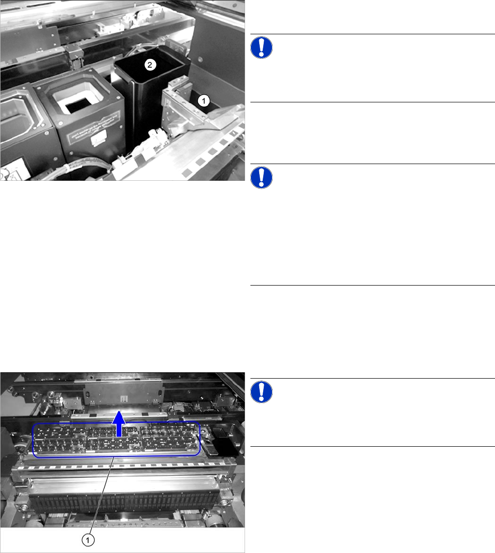
► Remove the nozzle reject bin (1). A message should
immediately appear on the control panel.
NOTICE!
If no message appears, have the safety circuit checked
and any damaged components replaced by authorized
personnel or the SIPLACE Service team.
► Reinsert the nozzle reject bin.
► Remove the component reject bin (2). A message
should immediately appear on the control panel.
NOTICE!
Monitoring the component reject bin is optional.
If no message appears, check whether this option is in
-
stalled on your system.
If the option is installed and no message appears, have
the safety circuit checked and, if required, any damaged
components replaced by authorized personnel or the
SIPLACE Service team.
► Reinsert the component reject bin.
► Repeat the procedure for all reject bins.
NOTICE!
Twin magazines are permanently fixed and cannot be re
-
moved. For this reason, this check is not applicable for
Twin magazines.
► Remove the nozzle magazines.
► Close the covers and press the Start button.
⇨ Depending on the station software, the station must
display all removed nozzle magazines.
Major Maintenance
Maintenance Tasks for Base Machine 5.2.3 Performing Maintenance Tasks
36 Maintenance Manual SIPLACE X Series
5.2.3.2
5.2.3.2 Cleaning the Gas Pressure Shock Absorbers on the Protective Covers
Cleaning the Gas Pressure Shock Absorbers on the Protective Covers
5.2.3.3
5.2.3.3 Check/replace the gas pressure shock absorbers on the protective covers
Check/replace the gas pressure shock absorbers on the protective covers
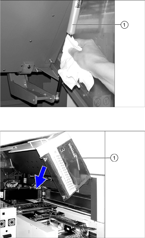
► Open the protective covers.
► Wipe the sliding surfaces of the gas pressure shock
absorbers (1) clean with a lint-free cloth.
► There should be no oil visible on the pistons: other
-
wise replace the gas pressure shock absorbers.
For removal and installation details, read the service
manual for your machine.
► Close the machine safety covers.
► Open the protective cover (1).
► Pull the protective cover approx. 30 cm downwards
and then release it again.
If the cover does not open completely again and if
there is play in the uppermost position (approx. 20
mm), replace the gas pressure shock absorbers.
For removal and installation details, refer to the Ser
-
vice manual for your machine.
► Pull the protective cover vertically to a position be
-
tween the top and bottom positions and then release
it again.
The cover must stay in position without help. If it clos
-
es on its own, replace the gas pressure shock ab
-
sorbers.
For removal and installation details, read the service
manual for your machine.
► Close the protective cover.
► Repeat these steps for all protective covers.