00190585-04.pdf - 第36页
SIPLACE 80 F4/(F4-6)/F5 1 Retrof itting Instructions for Coplanarity Option Edition 05/99 i - ii Figures Fig. 1 .1.1 Overv iew of t he Machin e 80 F 4/(F4-6)/F 5 (with Optional WPC) an d Mounting L ocation o f the Cop la…

1 Retrofitting Instructions for Coplanarity Option SIPLACE 80 F4/(F4-6)/F5
Edition 05/99
i - i
Contents
1.1 Overview of Retrofitting . . . . . . . . . . . . . . . . . . . . . . . . . . . . . . . . . . . . . . . . . . . . . . . . . . . . . . . . . . 1
1.2 Safety Instructions. . . . . . . . . . . . . . . . . . . . . . . . . . . . . . . . . . . . . . . . . . . . . . . . . . . . . . . . . . . . . . . 2
1.2.1 Definitions. . . . . . . . . . . . . . . . . . . . . . . . . . . . . . . . . . . . . . . . . . . . . . . . . . . . . . . . . . . . . . . . 4
1.3 Preconditions. . . . . . . . . . . . . . . . . . . . . . . . . . . . . . . . . . . . . . . . . . . . . . . . . . . . . . . . . . . . . . . . . . . 5
1.4 Retrofitting kit, Tools Required, etc. . . . . . . . . . . . . . . . . . . . . . . . . . . . . . . . . . . . . . . . . . . . . . . . . 5
1.5 Circuit Diagrams including Views for Control Unit . . . . . . . . . . . . . . . . . . . . . . . . . . . . . . . . . . . . 6
1.6 Mechanical and Electrical Installation . . . . . . . . . . . . . . . . . . . . . . . . . . . . . . . . . . . . . . . . . . . . . . 11
1.6.1 Information about the Initial Situation at the Machine. . . . . . . . . . . . . . . . . . . . . . . . . . . 11
1.6.2 Preparatory Steps . . . . . . . . . . . . . . . . . . . . . . . . . . . . . . . . . . . . . . . . . . . . . . . . . . . . . 12
1.6.3 Installing the Option . . . . . . . . . . . . . . . . . . . . . . . . . . . . . . . . . . . . . . . . . . . . . . . . . . . . 13
1.6.3.1 Running and Connecting "Sensor Cable Coplanarity",
Adapting Cable Run for Flip-Chip-Camera,
Installing the Coplanarity Sensor . . . . . . . . . . . . . . . . . . . . . . . . . . . . . . . . . . . . . . . . . . 13
1.6.3.2 Conveyor Trench: Adapt and Install New Dust Cover . . . . . . . . . . . . . . . . . . . . . . . . . . 16
1.6.3.3 Installing the Control Unit: "Coplanarity Processing Unit"
(possibly including Connector X98),
Running and Connecting the Cable at the Control Unit . . . . . . . . . . . . . . . . . . . . . . . . . 16
1.6.3.4 Running the Cable "Coplanarity - Terminal Panel" and
the Cable Harness "Coplanarity" (X98 -> Power Pack),
Completely Wiring the 15-pin X98 Connector . . . . . . . . . . . . . . . . . . . . . . . . . . . . . . . . 17
1.6.4 Final Steps . . . . . . . . . . . . . . . . . . . . . . . . . . . . . . . . . . . . . . . . . . . . . . . . . . . . . . . . . . . 18
1.7 Checking the Safety Circuit . . . . . . . . . . . . . . . . . . . . . . . . . . . . . . . . . . . . . . . . . . . . . . . . . . . . . . 19
1.7.1 Interruptions in Protection which must be Checked . . . . . . . . . . . . . . . . . . . . . . . . . . . 19
1.7.2 Steps in the Check . . . . . . . . . . . . . . . . . . . . . . . . . . . . . . . . . . . . . . . . . . . . . . . . . . . . . 19
1.8 Configuring the Option (at Line Computer and Station Computer) and Putting It into Service 21
1.8.1 Line Computer: Configuring the Coplanarity Option. . . . . . . . . . . . . . . . . . . . . . . . . . . . 21
1.8.2 Line Computer: Consistency Check of All Set-Ups . . . . . . . . . . . . . . . . . . . . . . . . . . . . 21
1.8.3 Line Computer: Activating the Option "Coplanarity" for Individual Components . . . . . . 21
1.8.4 Line Computer: Activating the Coplanarity Measurement Capability for the Models . . . 22
1.8.5 Feasibility Test . . . . . . . . . . . . . . . . . . . . . . . . . . . . . . . . . . . . . . . . . . . . . . . . . . . . . . . . 22
1.8.6 Station Computer: Configuring the Coplanarity Option . . . . . . . . . . . . . . . . . . . . . . . . . 22
1.8.6.1 Procedure for Version 403.04. . . . . . . . . . . . . . . . . . . . . . . . . . . . . . . . . . . . . . . . . . . . . 22
1.8.6.2 Procedures with Versions > 404.01 . . . . . . . . . . . . . . . . . . . . . . . . . . . . . . . . . . . . . . . . 23
1.8.7 Calibrating with the SITEST Program. . . . . . . . . . . . . . . . . . . . . . . . . . . . . . . . . . . . . . . 23
1.8.7.3 Preconditions . . . . . . . . . . . . . . . . . . . . . . . . . . . . . . . . . . . . . . . . . . . . . . . . . . . . . . . . . 24
1.8.7.4 V 403.04: Performing Calibration . . . . . . . . . . . . . . . . . . . . . . . . . . . . . . . . . . . . . . . . . . 24
1.8.7.5 >
V 404.01: Performing Calibration . . . . . . . . . . . . . . . . . . . . . . . . . . . . . . . . . . . . . . . . 24
1.8.8 In Case of Problems or Errors:
Check Position of Coplanarity Sensor (>
V 403.xx) . . . . . . . . . . . . . . . . . . . . . . . . . . . . 25
1.8.8.6 Procedure (>
V 403.xx) . . . . . . . . . . . . . . . . . . . . . . . . . . . . . . . . . . . . . . . . . . . . . . . . . 26
1.8.8 Sequence Data Protocol (German: ADP). . . . . . . . . . . . . . . . . . . . . . . . . . . . . . . . . . . . 28
1.8.8.1 Output of an Error Message while Executing the Test Command:. . . . . . . . . . . . . . . . . 28
1.8.8.2 Copy of the Sequence Data Protocol (ADP) with Explanation of the Lines . . . . . . . . . . 28
1.8.8.3 Translating the Texts in the ADP File. . . . . . . . . . . . . . . . . . . . . . . . . . . . . . . . . . . . . . . 31
SIPLACE 80 F4/(F4-6)/F5 1 Retrofitting Instructions for Coplanarity Option
Edition 05/99
i - ii
Figures
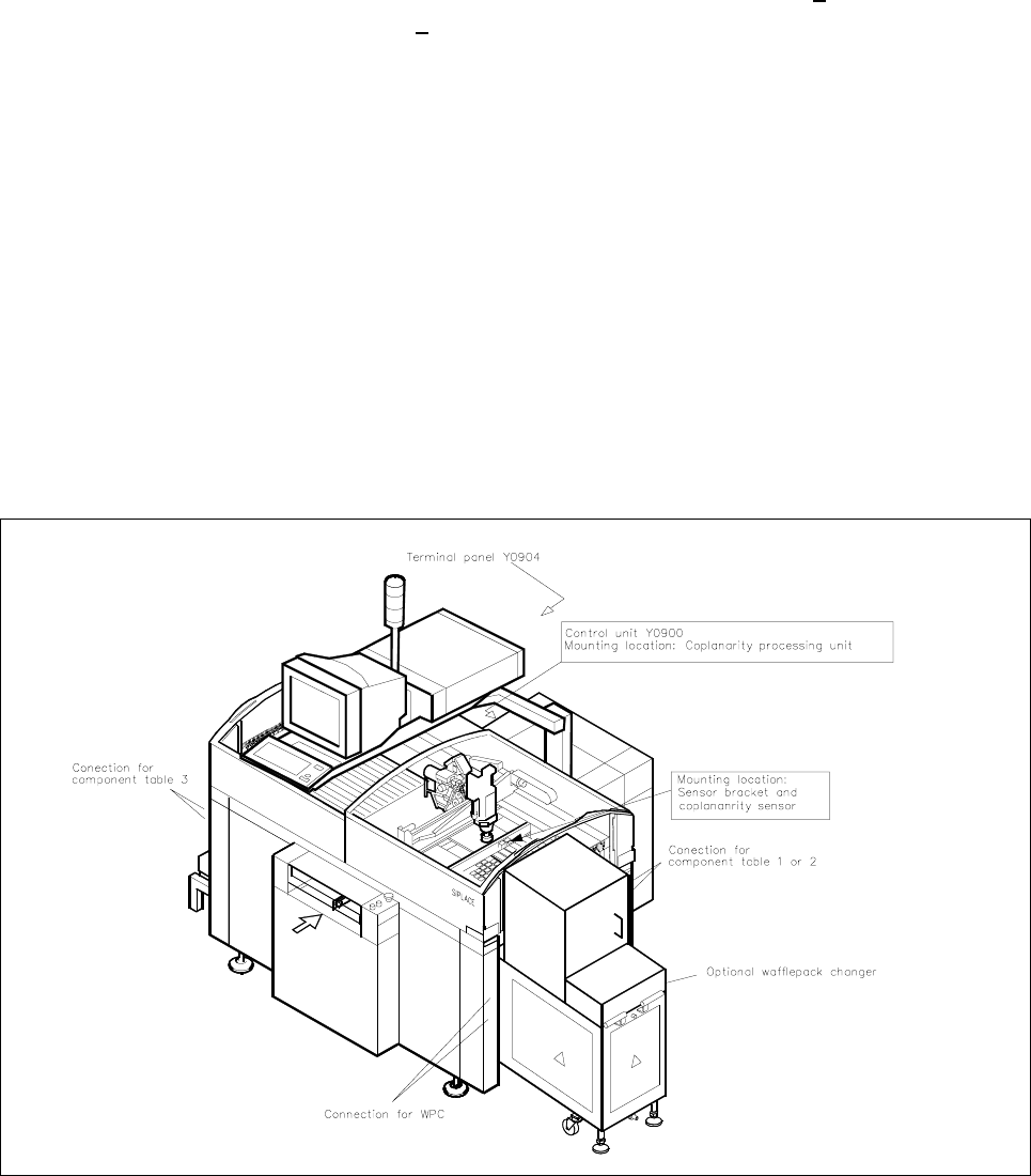
Fig. 1.1.1 Overview of the Machine 80 F4/(F4-6)/F5 (with Optional WPC) and
Mounting Location of the Coplanarity Option . . . . . . . . . . . . . . . . . . . . . . . . . . . . . . . . .1
Fig. 1.2.1 Laser Warning Plates on the Coplanarity Sensor . . . . . . . . . . . . . . . . . . . . . . . . . . . . . .3
Fig. 1.5.1 Cable: Coplanarity Option - Terminal Panel, Item No. 00336795-02
(Sensor -> Front of Control Unit) . . . . . . . . . . . . . . . . . . . . . . . . . . . . . . . . . . . . . . . . . .6
Fig. 1.5.2 Sensor Cable: Coplanarity Option, Item No. 00336793-01
(Sensor -> Front of Control Unit) . . . . . . . . . . . . . . . . . . . . . . . . . . . . . . . . . . . . . . . . . .7
Fig. 1.5.3 Cable: Coplanarity Option - Machine Controller, Item No. 00336796-01
(Control Unit -> Control Unit) . . . . . . . . . . . . . . . . . . . . . . . . . . . . . . . . . . . . . . . . . . . . .8
Fig. 1.5.4 Test Connector: Coplanarity Option, Item No. 00337304-01 . . . . . . . . . . . . . . . . . . . . .8
Fig. 1.5.5 Control Unit: Connector X98 and Cable "Coplanarity Option"
(X98 -> Power Supply Unit (Item No. 00342894-01). . . . . . . . . . . . . . . . . . . . . . . . . . . 9
Fig. 1.5.6 Control Unit: Installing the "Coplanarity Option
Processing Unit " including the Cable . . . . . . . . . . . . . . . . . . . . . . . . . . . . . . . . . . . . . .10
Fig. 1.6.1 Installation of the Coplanarity Sensors (Laser) . . . . . . . . . . . . . . . . . . . . . . . . . . . . . . .15
Fig. 1.8.1 Menu Structure “Software Options” (Station Computer) . . . . . . . . . . . . . . . . . . . . . . . 26
Fig. 1.8.2 Monitor Image, Order of Scanning of Lead Rows . . . . . . . . . . . . . . . . . . . . . . . . . . . . . 28
1 Retrofitting Instructions for Coplanarity Option SIPLACE 80 F4/(F4-6)/F5
1.1 Overview of Retrofitting Edition 05/99
1 - 1
1 Retrofitting Instructions Coplanarity
Option on SIPLACE 80 F4/(F4-6)/F5
1.1 Overview of Retrofitting
The new model of the “Coplanarity” option can be retrofitted on SIPLACE F4 with SW > V 403.04 and on
SIPLACE F
5 (F4-6) with software version > 404.01.
With no further protective measures, the
laser radiation of the new coplanarity sensor is in accordance with
Laser Class
2.
When protective measures are taken, i.e., when the laser is properly installed and the machine is closed, the
laser is in accordance with Laser Class
1 (see Safety Instructions in Section 1.2). Aside from the existing
identifying markings on the coplanarity sensor itself (see Section 1.2), no additional warning signs are
required.
Make certain that the
customer will have a 2nd strong person available throughout the retrofitting process
to
assemble and disassemble the component table and the cutter (see Section 1.2).
The flip-chip and IC camera
remain mounted during the retrofitting. A recalibration of these cameras is there-
fore not necessary. In the event the earlier model of the coplanarity option had a defect, the new model must
be installed. During this process, the old
coplanarity laser module including bracket and coplanarity assembly
(in the control unit) is removed. The current “old” sensor cable is run back inside the machine base such that
it is short-circuit-proof. The cable for the +5 V power supply is not altered (see Section 1.6.1).
Fig. 1.1.1 Overview of the Machine 80 F4/(F4-6)/F5 (with Optional WPC) and Mounting Location of the Coplanarity Option