00190585-04.pdf - 第47页
1 Retrofitting Instructions for Coplanarity Option SIPLACE 80 F4/(F4-6)/F5 1.6 Mechanical and Electrical Installation Edition 05/99 1 - 11 Key for Fig. 1.5.6 (to your left): 1) Front subp anel, 2) 2 g uide rai ls an d 2 …
SIPLACE 80 F4/F5 1 Retrofitting Instructions for Coplanarity Option
Edition 05/99 1.5 Circuit Diagrams including Views for Control Unit
1 - 10
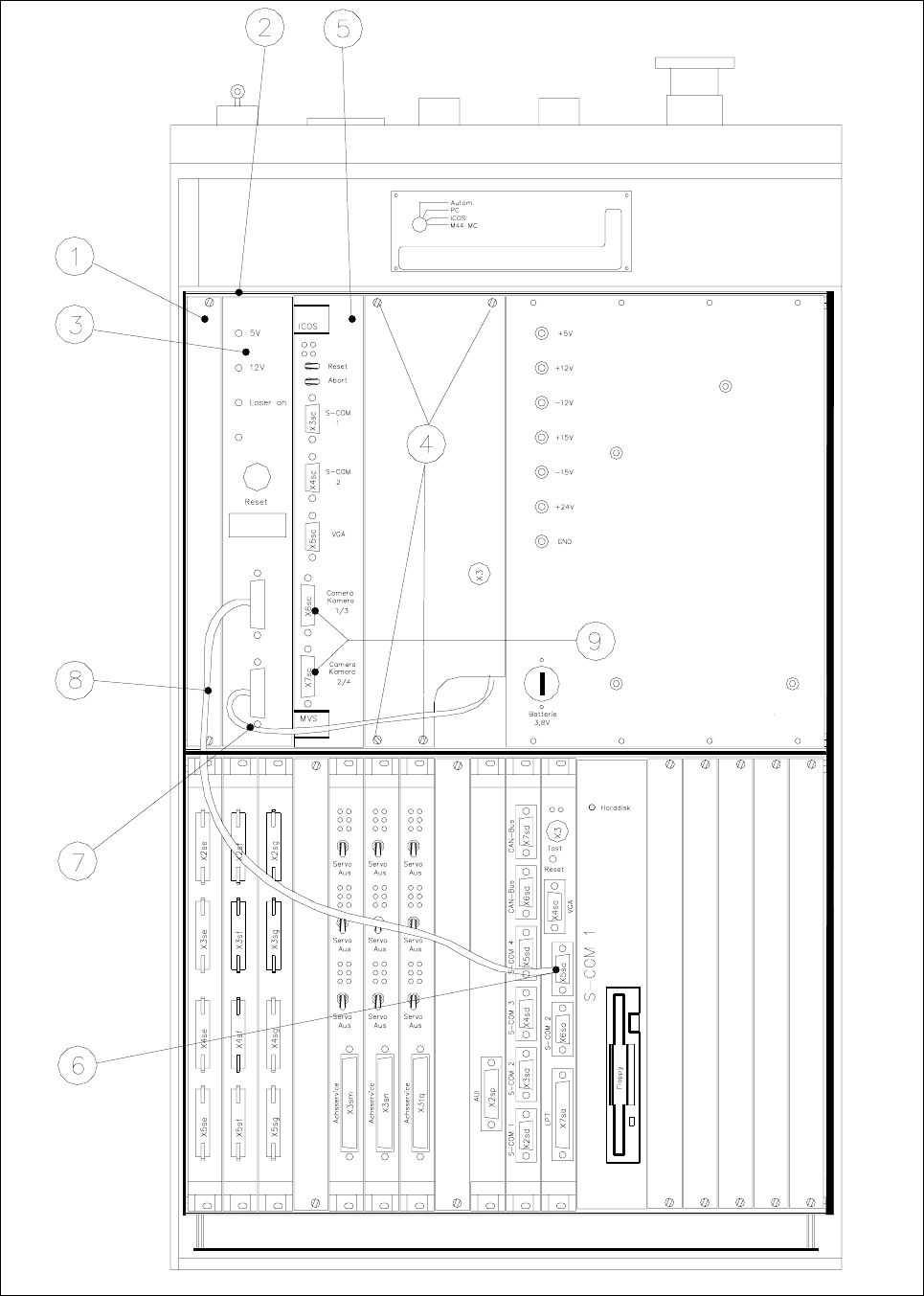
Fig. 1.5.6 Control Unit: Installing the "Coplanarity Processing Unit " including the Cables

1 Retrofitting Instructions for Coplanarity Option SIPLACE 80 F4/(F4-6)/F5
1.6 Mechanical and Electrical Installation Edition 05/99
1 - 11
Key for Fig. 1.5.6 (to your left):
1) Front subpanel, 2) 2 guide rails and 2 contact springs
Fasteners: 2 collar screws, slotted M2.5 x 11 per rail (see Fig. 1.5.5)
3) Control unit : coplanarity processing unit and 4) Fasteners for cover plate
15-pin connector on back of control unit (see Fig. 1.5.5) 4 Torx screws)
5) ICOS (on older control units the ICOS may also 6) Machine controller, COM 1
be located in the bottom row of plug-in slots (V 24 interface)
7) Sensor cable coplanarity 8) Cable: Coplanarity - machine
controller
9) These 2 connectors project over on the left
and must therefore be dismantled
before
installing the coplanarity processing unit.
1.6 Mechanical and Electrical Installation
DANGER O O O
Turn the machine off and pull out the mains plug to the machine.
Comply with
all of the safety instructions in Section 1.2 !
Observe the sequence of the steps in the job.
No bridging of safety equipment is to be performed.
Operating the laser (sensor) outside the machine is not permitted.
1.6.1 Information about the Initial Situation at the Machine
NOTE
SIPLACE machines with the
following version of control unit are already pre-equipped for the installation
of the
new model of the coplanarity (version identification: see Fig. 1.5.5):
- Version of control unit
F4: > 00324340-07
- Version of control unit
F4-6: > 00331294-03
- Version of control unit F5: > 00341851-03
Different initial situations may exist when retrofitting the
new model of the coplanarity option.
- 1st Situation
Machine with a control unit which is an
earlier model than specified above and the earlier model of the
coplanarity option is installed.
This means:
- The old cable running through the inside of the machine base to the laser must be run back inside the

SIPLACE 80 F4/F5 1 Retrofitting Instructions for Coplanarity Option
Edition 05/99 1.6 Mechanical and Electrical Installation
1 - 12
- The 5 V-cable from the control unit to terminal panel 904 can remain connected.
- The coplanarity laser module including bracket must be removed from the machine.
- 2nd Situation
Machine with a control unit which is an earlier model than specified above and the coplanarity option
was
not previously installed.
This means
- Machine with version no. < 90: There is nothing to take into consideration, since no equipment which
has been prepared in advance is available for the old coplanarity module.
- Machine > version no. 90:
The cable to the laser module prefitted in advance at the factory for the old coplanarity module is left
unchanged.
- The 5 V cable from the control unit to terminal panel 904 is left unchanged, including the wiring.
- 3rd Situation
Machine with a control unit which is a some ore later model than specified above: In this version and
later the machine
is pre-equipped for the installation of the new coplanarity sensors -> see marking with
*) in Section 1.4
:
- Already installed in the control unit are the 2 guide rails, each with 2 contact springs (see Fig. 1.5.6 ->
2) and connector X98 (see Fig. 1.5.5) for the coplanarity module.
- The "sensor cable coplanarity" (sensor -> control unit: see Fig. 1.5.2) and the cable "coplanarity-termi-
nal panel" (see Fig. 1.5.1) is already been run inside the machine base.
- The cable harness of the cable "coplanarity" (see Fig. 1.5.5) has already been run from connector X98
to the power pack and is completely wired.
1.6.2 Preparatory Steps
● Press the “EMERGENCY OFF” button.
● Make certain that the key-operated switch is locked.
● Turn the machine off at the main switch and isolate the machine from the mains (see DANGER text
above).
● If a wafflepack changer is installed, unplug both connectors of the WPC on left of the machine base
(
first the power supply connector and then the interface connector).
Run the WPC out of the machine.
● Remove the cover plate between component table and the PCB conveyor.
DANGER O O O
There must
always be a 2nd strong person available to disassemble the cutter and the component table
(1 or 2) because the component table and the cutter are very heavy
reater risk of accident during disassembly/assembly due to the blades of the cutter (see DANGER text
in Section 1.2). You will require the pertinent service manual to disassemble the cutter (see Section 1.4, under
"Documentation").