00190585-04.pdf - 第60页
SIPLACE 80 F4/F5 1 Retrof itting Instructions for Coplanarity Option Edition 05/99 1.8 Configuring the Option (at Line Computer and Station Computer) and Putting It into Service 1 - 24 1.8.7.3 Preconditions ● A side fr o…

1 Retrofitting Instructions for Coplanarity Option SIPLACE 80 F4/(F4-6)/F5
1.8 Configuring the Option (at Line Computer and Station Computer) and Putting It into Service Edition 05/99
1 - 23
1.8.6.2 Procedures with Versions > 404.01
DANGER O O O
Where retrofitting is involved, no one except the Siemens service engineer is permitted to turn the
machine on.
● Turn the machine on and start the SITEST program.
● Carry out the “total reference run” in the SITEST program.
● Select the option “Settings” in the pulldown menu. Select the “Machine configuration ...” menu.
● In the dialog field which is opening, select the line “Coplanarity" by clicking twice or “Edit”.
● Select the module. Buttons available: None / LCM150 / ILD 2000:
-> Select the button "
ILD 2000" (= new sensor) -> Confirm "Accept" (2 x).
● In the SITEST main window the message appears “The machine must be turned off in order to ...”.
In response to the question “Store?” enter “YES” and confirm the message window:
- The station computer shut down automatically.
● Carry out a restart of the station (machine OFF and then back ON).
● The coplanarity option is transferred to the station.
Due to the previous selection of the new sensor, the station “knows”, e.g., the
X-Y-Z-position of the new
sensor ( X- 444000, Y = 595000, Z = 17000) and the new speed factor (400).
1.8.7 Calibrating with the SITEST Program
DANGER O O O
While the machine is undergoing retrofitting, it is to be put into service by no one except the Siemens service
engineer. Bridging of protective equipment is not permitted.
For all subsequent jobs the key-operated switch must be locked.
CAUTION O
The calibrating sequence subsequently started via SITEST is
just utilized here to turn on the sensor, i. e.,it is
not to be stored.
NOTE
In order to calibrate the coplanarity sensor (laser) the new coplanarity option must be activated at the line
computer (see Section Fig. 1.8.1 and following) and must have been entered at the station (see Section
1.8.6). After this a station restart must have been carried out.

SIPLACE 80 F4/F5 1 Retrofitting Instructions for Coplanarity Option
Edition 05/99 1.8 Configuring the Option (at Line Computer and Station Computer) and Putting It into Service
1 - 24
1.8.7.3 Preconditions
● Aside from coplanarity, the machine is completely calibrated.
1.8.7.4 V 403.04: Performing Calibration
● Procedure: As described below for Version 404.01 with the following difference:
NOTE
If the button COPLANARITY is
inactive, the option was not set at the line computer (see
Section 1.8.3) or the station restart was not performed.
1.8.7.5 > V 404.01: Performing Calibration
● Turn the machine on and start the SITEST program.
● Carry out the “total reference run” in the SITEST program.
● Pick up nozzle no. 417 with the IC head.
● Select the function menu “IC HEAD” -> “COPLANARITY”
NOTE
If the button COPLANARITY is
inactive, the button for “NONE” (module) was accidentally
actuated while activating the option at the line computer (see Section 1.8.3) or the station was not restarted.
The display of the initial positions of the new coplanarity sensor follows (configuration data)
X = 444000 Y = 595000 Z = 17000
● Select the function menu -> “CALIBRATE MODULE”
● When the request appears on the screen, place the coplanarity calibration tool in the middle of the cal-
ibration tool pocket on the stationary side of the conveyor.
● Close the protective hoods and actuate the “Start” button.
● The calibration starts automatically. The calibration values determined are displayed.
Possible error messages during this process:
- X-Y-position not located. Possible causes:
- Position of coplanarity sensor is wrong because:
- In case of
V403.04: X-,Y- and Z-position incorrectly entered in real.ma (see Section 1.8.6.1).
- In case of
404.01: Wrong, i.e., old coplanarity module ("LCM150") - and thus the old
X-, Y- (and Z) -position - were entered.
- In the case of machines with
dual conveyors (left-hand or right-hand conveyor side = stationary):
distance washers (
total 2 mm thick) between the sensor bracket and the optional carrier
for nozzle changer were not installed or more/less than two disks per screw were installed ->
1 Retrofitting Instructions for Coplanarity Option SIPLACE 80 F4/(F4-6)/F5
1.8 Configuring the Option (at Line Computer and Station Computer) and Putting It into Service Edition 05/99
1 - 25
see Fig. 1.6.1 -> 5.
- In case of machines with a
single conveyor: Distance washers were installed at the
above location ( = incorrect).
- Focus outside of tolerances
Possible causes:
- Calibration tool damaged or not picked up.
- In case of V 403.04: Z-position for coplanarity sensor incorrectly entered in the file real.ma.
- Diameter of calibration tool not within tolerances
Possible cause:
- Nozzle projects over calibration tool -> Wrong nozzle picked up (= not 417).
● If desired, actuate the “Display” button to see the measured values.
● Terminate the menu “COPLANARITY”. Terminate the SITEST program.
● Answer “YES” to the question being displayed: “Store the data?”
The offset values for X, Y and Z are entered in the
real.ma data under coplanarity_2_x /.... _y /.... _z .
● Press EMERGENCY OFF and remove the calibration tool.
● As the final step, check whether the IC camera and flip-chip camera function.
1.8.8 In Case of Problems or Errors:
Check Position of Coplanarity Sensor (>
V 403.xx)
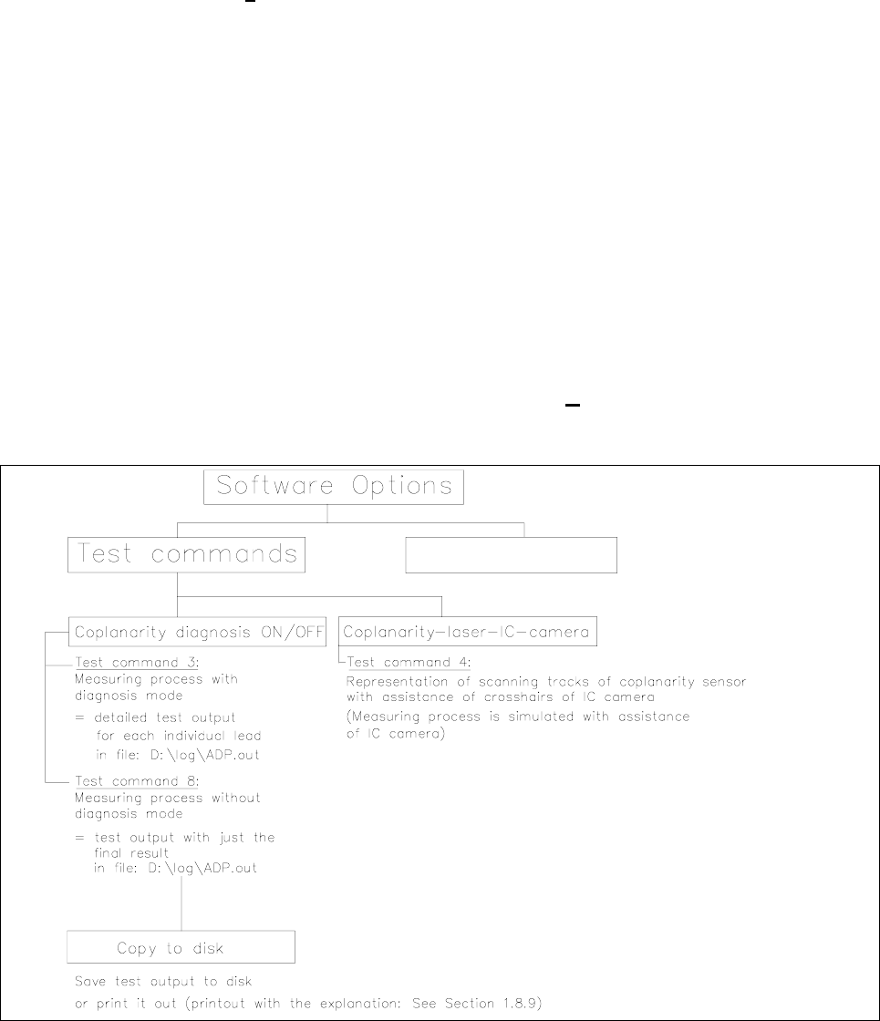
Fig. 1.8.1 Menu Structure “Software Options” (Station Computer)