161页面.pdf - 第145页
Enc los ed - Saf e ty sw itch- di s co nn ec to rs Notes: Engineering: Maintenance, repair and safety switches all have the same electrical function. They are designed to safely isolate electrical installations (loads) f…
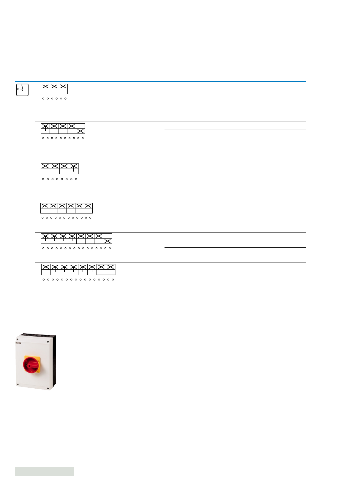
Enclosed - Safety switch-disconnectors with auxiliary contacts
Front
plate
Auxiliary
contacts
Suitable for
export to
North America
(US and
Canada)Contact sequence
Number
of poles N/0 N/C
Rated
current Part number
Article
number
Pack
qty
3 0 0 25 A P1-25/I2-SI 207313 1 X
32 A P1-32/I2-SI 207329 1 X
63 A P3-63/I4-SI 207361 1 X
80 A P3-80/I5-SI EP-400993 1 X
100 A P3-100/I5-SI 207386 1 X
3 1 1 25 A P1-25/I2-SI/HI11 207310 1 X
32 A P1-32/I2-SI/HI11 207331 1 X
63 A P3-63/I4-SI/HI11 207363 1 X
80 A P3-80/I5-SI/HI11 EP-400994 1 X
100 A P3-100/I5-SI/HI11 207388 1 X
3+N 0 1 25 A P1-25/I2-SI/N 207312 1 X
32 A P1-32/I2-SI/N 207333 1 X
63 A P3-63/I4-SI/N 207365 1 X
80 A P3-80/I5-SI/N EP-400996 1 X
100 A P3-100/I5-SI/N 207390 1 X
6 0 0 63 A T5B-3-8342/I4-SI 207250 1 X
100 A T5-3-8342/I5-SI 207447 1 X
6 1 1 63 A T5B-4-15682/I4-SI 207254 1 X
100 A T5-4-15682/I5-SI 207285 1 X
6 2 0 63 A T5B-4-8903/I4-SI 207258 1 X
100 A T5-4-8903/I5-SI 207289 1 X
FS 908
ON
OFF
1
2
3
4
5
6
01
1
2
3
4
5
6
13
14
01
21
22
1
2
3
4
5
6
N
N
01
1
2
3
4
5
6
7
8
9
10
01
11
12
1
2
3
4
5
6
7
8
01
9
10
11
12
13
14
15
16
1
2
3
4
5
6
7
8
01
9
10
11
12
13
14
15
16
Switch-disconnectors tted in polycarbonate Ci-K Enclosure, with emergency switch o/emergency stop function
Photo is representative
See further details about the safety switch-disconnectors page 145
Note: All the SI handles are padlockable
144
EATON P Switch-disconnectors and T Rotary cam switches CA042001EN
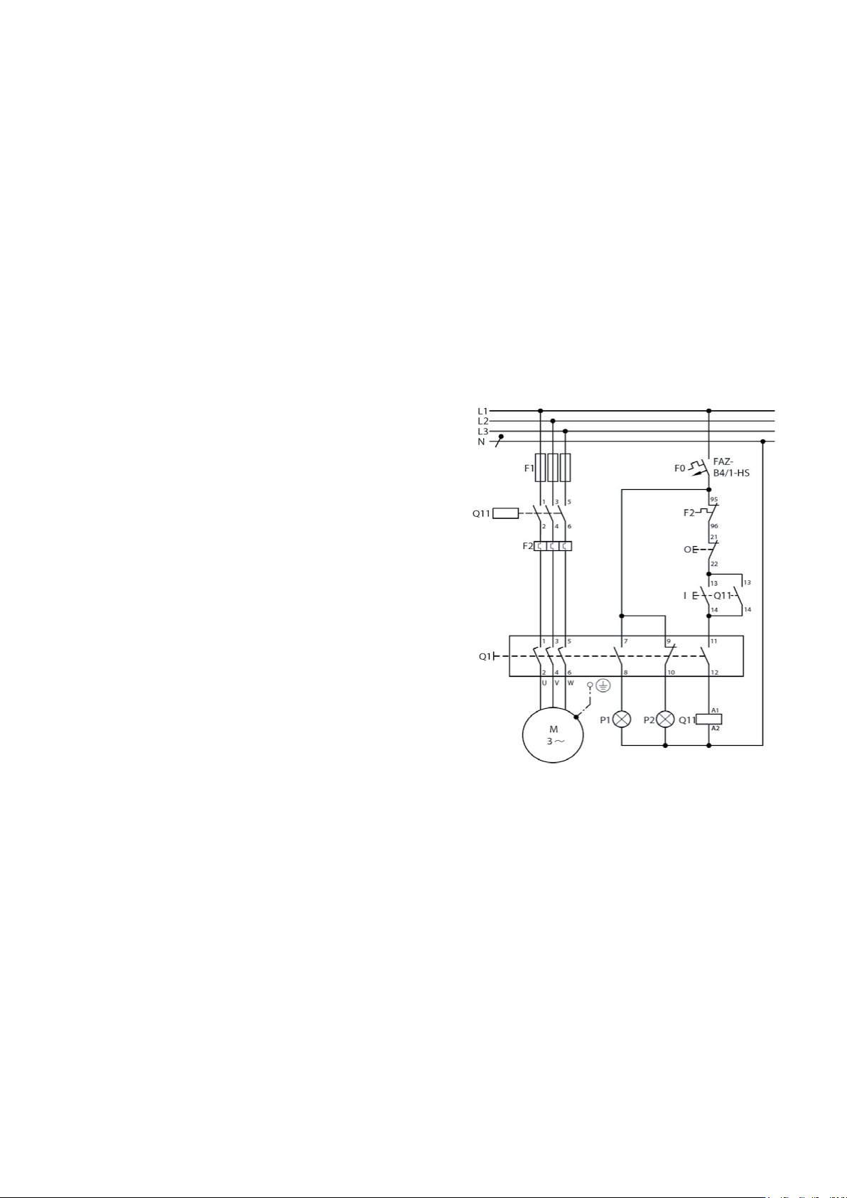
Enclosed - Safety switch-disconnectors
Notes:
Engineering:
Maintenance, repair and safety switches all have the same electrical function. They
are designed to safely isolate electrical installations (loads) from mains power
during maintenance and repair work and to ensure that a hazard does not arise
which endangers personnel, machinery and production materials.
A safety switch is an additional enclosed main switch = isolator dedicated to an
individual electrical load and mounted in the immediate vicinity of the motor of
the electrical load. This is particularly important is there is any danger of the main
switch being inadvertently operated.
Application
By using up to 3 padlocks, each fitter/electrician involved can protect themselves
by preventing unauthorised personnel from switching the unit on.
Maintenance/manual override switches are simply additional enclosed main
switches with a padlocking feature.
Enclosed main switch with padlocking facility.
Features
• Safety switches are always housed in insulated enclosures and have an inscrip-
tion saying ‘Safety switches’ on a bright orange label.
• Switches to be used in emergency stop switching have a red handle and yellow
locking collar in accordance with STOP category 0 (as per IEC/EN 60204/VDE
0113).
• If the switch is not approved for emergency stop switch, both parts will be black
(‘SW’ part no. suffix).
• The cover and handle are interlocked by fitting a padlock.
Selection
The switches must be selected according to the following performance
specifications:
1) According to motor switching capacity, when the switch is fitted in such a way
that the operator may use it for operational ON and OFF switching
2) The rating data always applies to 3 poles. When the motor rating is divided
between 6 poles, such as for star-delta switching, a 6 pole switch can be used to
control 1.73 time the rated power.
3) If the switch has a load shedding Contact (LA), you can select the appropriate
switch according to the uninterrupted current. The load switching contact is
an auxiliary contact, which closed in the ON position and opens early when
switching off, so that a contactor located in the circuit takes over the switching
duty and the maintenance/safety switch operates at zero load. When switching
on, the load-shedding contact closes later than or at the same time as the main
contacts. With P and T switches this is the N/0 auxiliary contact.
4) The ‘ON’ position can be locked with a padlock (by altering the handle).
This is not permissible for switches with a red/yellow handle.
Safety switches with load shedding and signaling
145EATON P Switch-disconnectors and T Rotary cam switches CA042001EN
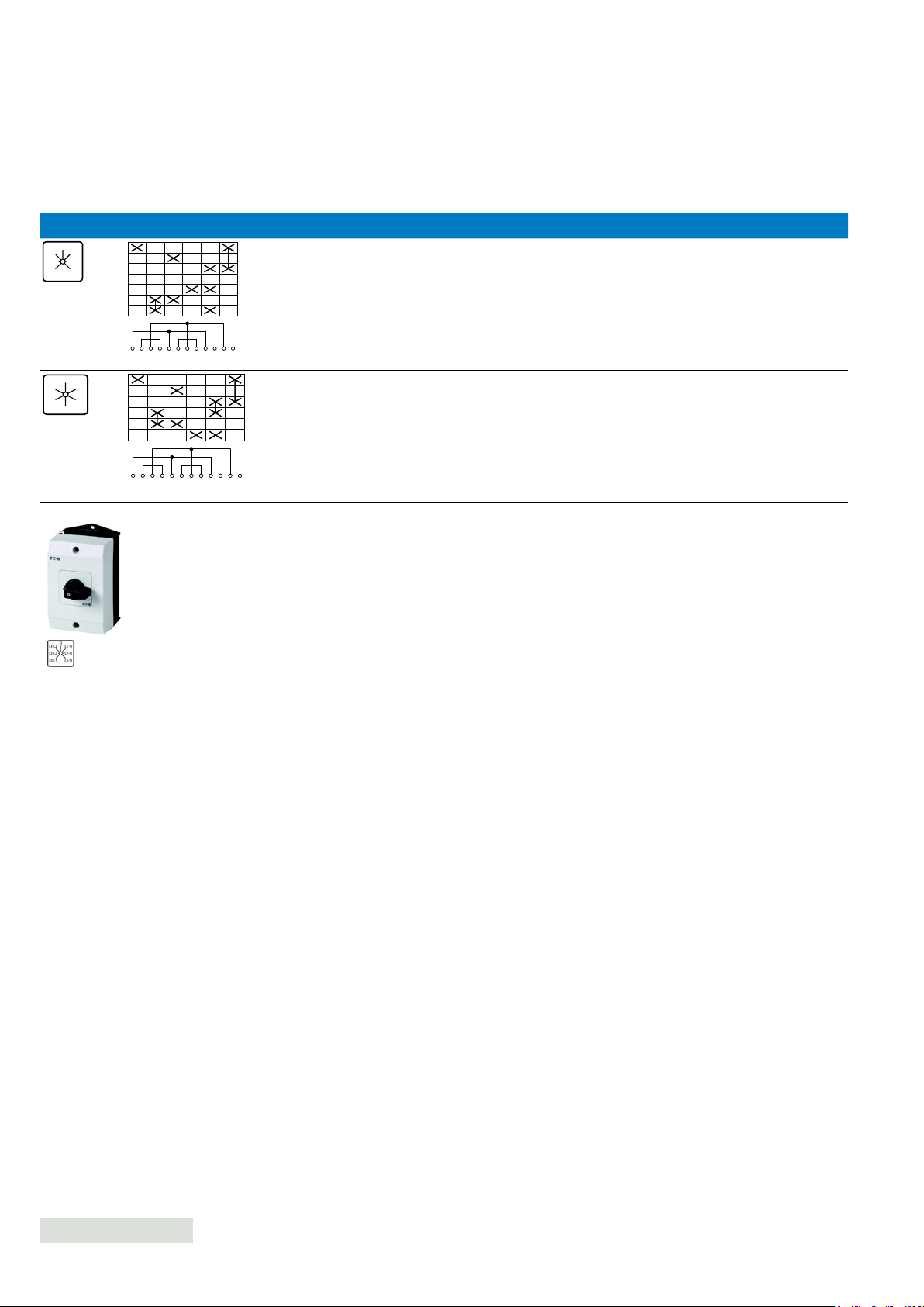
Enclosed - Selector switch-disconnectors
Contact sequence
Suitable for
export to
North America
(US and
Canada)
Padlockable
handleFront plate Number of poles
Rated
current Part number
Article
number
Pack
qty
Voltmeter switch-disconnector
3 x phase-phase
3 x phase-N with 0 position
20 A T0-3-8007/I1 207120 1
X
3 x phase-phase
3 x phase-N without 0 position
with complete rotation in both
directions
20 A T0-3-15924/I1 207119 1
X
L1-L2
FS 1410759
0
L2-L3
L3-L1
L1-N
L2-N
L3-N
L1-L2
L2-L3
L3-L1
L1-N
L2-N
L3-N
FS 164721
1
2
3
4
5
6
7
8
9
10
11
12
L3-L1
L2-L3
L1-L2
0
L1-N
L2-N
L3-N
1
2
3
4
5
6
7
8
9
10
11
12
L1-L2
L2-L3
L3-L1
L1-N
L2-N
L3-N
207120
Switch-disconnectors tted in polycarbonate Ci-K Enclosure, without emergency switch o/emergency stop function
Photo is representative
146
EATON P Switch-disconnectors and T Rotary cam switches CA042001EN