161页面.pdf - 第175页
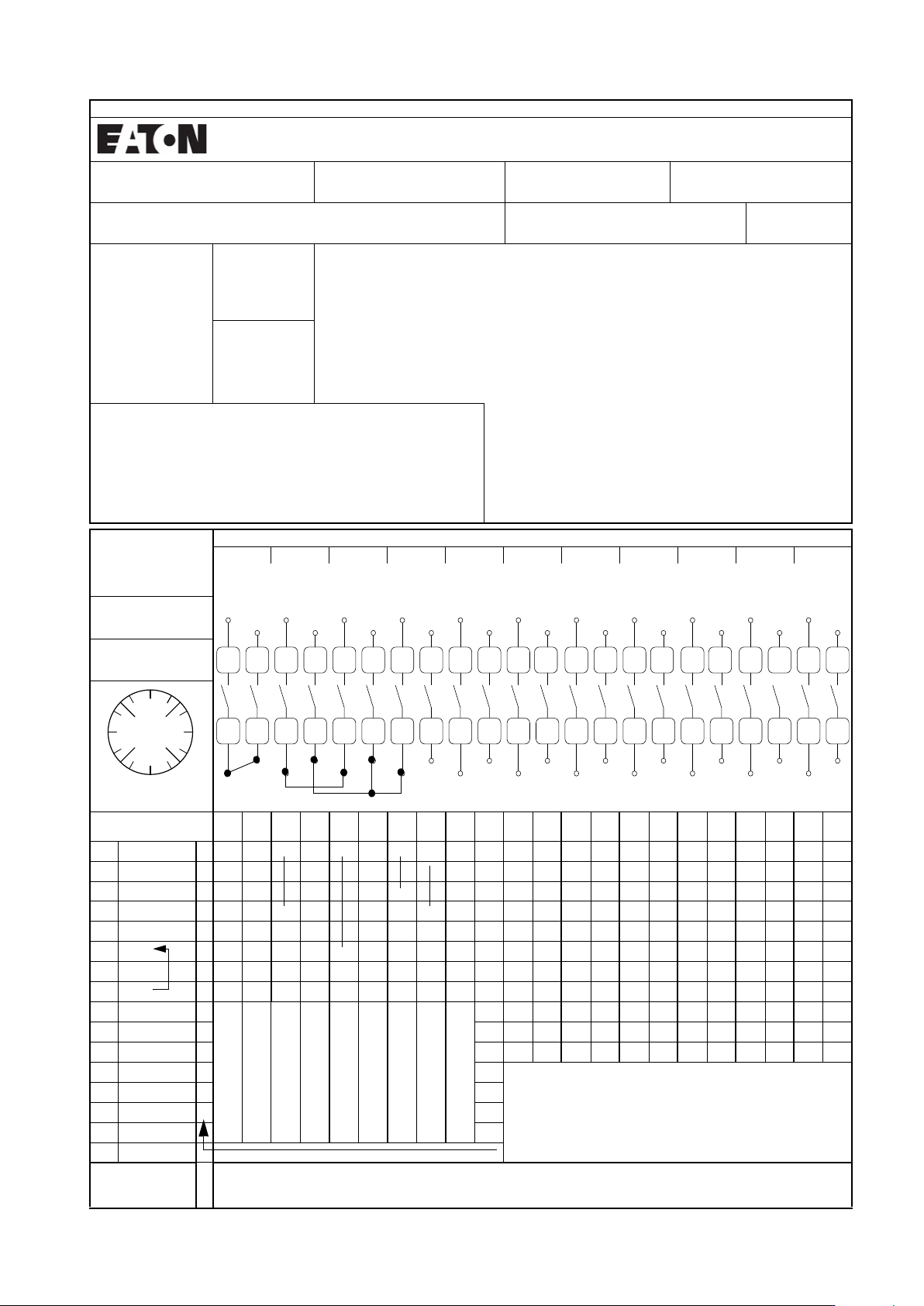
N o n s tanda r d Cam sw itch es and Sw itch- dis co nnec t ors Non-standard contact sequen ce ord ering example Binding documen t for ordering T cam switch combinations for the first time Order No.: 123456 Item: 7 Offic…

Non standard Cam switches and Switch-disconnectors
Ordering of non standard contact sequences
T.......... - .............................................. - .................................. / ............................................................... + ..................
Switch
size
Number of contacts units
(2 contacts per contact unit)
Contact sequence number Mounting form Accessories
Max units Contacts max. With country ID corresponding to the
country of manufacture.
Send completed forms (as shown page
175) if ordering for the first time. The
contact sequence number is specified
by the supplying factory. Specifying the
part no is enough when placing repeat
orders.
Flush mounting: /E Always specify
completely for
every order
For TM.../EZ
only +EZ/S
possible
TO 11 22 Centre mounting: /EZ (for T0, T3)
T3 11 22 Surface mounting: /I
(1)
T5B 10 20 Service distribution board mounting: /IVS (for T0)
T5 10 20 Rear mounting: /Z
TM 8 16 Flush mounting main switch EA/SVB
(2)
Surface mounting main switch: I../SVB
Rear mounting main switch: /V/SVB
(2)
Designs for: TM: /E/EZ or /IVS
Contact sequence
The adjacent form makes it easier to specify the contact sequence.
Switching angle
30, 45, 60, 90
o
Preferred angle: 60
o
For On-Off switches: 90
o
For main switches: 90
o
as FS 908
Changeover with interruption between 2 positions (ON-OFF-ON) not
permissible for T0, T3 and TM = 30
o
, 45
o
; for T5 (T5B) = 30
o
Star delta switch only with switching angle ≥ 60
o
Terminal marking
TM switches have consecutive terminal markings starting with 1.
Automatic (spring) return
The switching action is limited by a stop. The switch returns under spring
pressure to the last position. Where a switch has Automatic (spring) return
from both directions, a maximum of max. 3 positions can be traversed.
The Automatic (spring) return angle is ≤½ switching angle. A max of 6
contacts can be returned at the same time.
The switching angle of Automatic (spring) return TM mini rotary switch
must be ≥ 60
o
.
Fleeting contacts
The duration of the fleeting contact depends primarily on the actuation
speed. In order to actuate a contactor with a fleeting pulse, the switching
angle of the cam switch must not be less than 60
o
, since the pulse time can
be too short if the switching angle is smaller. Fleeting contact elements
always cooperate in both operating directions.
Complete rotation
Only possible with a total switching angle at 360
o
the direction of
switching can be either operating direction. The number of switch position
multiplied by the switching angle must be 360
o
, TM with 12 positions (one
every 30
o
) only available with complete rotation, not with stop.
Front plates
Front plates are part of the equipment supplied with a ‘first order of rotary
switch’ and therefore do not need to be ordered separately.
Number of contact units
Number of contact/2 = Round up to nearest whole number
The number chamber = contact unit (BE) has 1 or 2 contacts, each of which
is actuated by a cam.
In T5(B) there is a common cam for both contacts. Because of this, the
following applies for T5(B): If the total switching angle is less than 180
o
,
the contacts can be switched independently of each other. With switching
angles for greater than or equal to 180
o
, there can only be 2 contacts in the
same chamber, if their switching sequences are the same but are offset by
180
o
(e.g. TS5-4-8235 step switch)
Standard features
Same as cam switch with standard contact sequence.
Note: It is possible that the order of the contacts is altered due to technical reasons. For special switches, bridges are only
possible between an even or uneven number. Other connections must be made by the user installation.
(1) For T0-.../I1 max 4 contact units
For T3.../I2 max 5 contact units
(2) For T0 up to a max 8 contact = 4 BE
For T3: up to a max. of 12 contacts = 6 BE
174
EATON P Switch-disconnectors and T Rotary cam switches CA042001EN
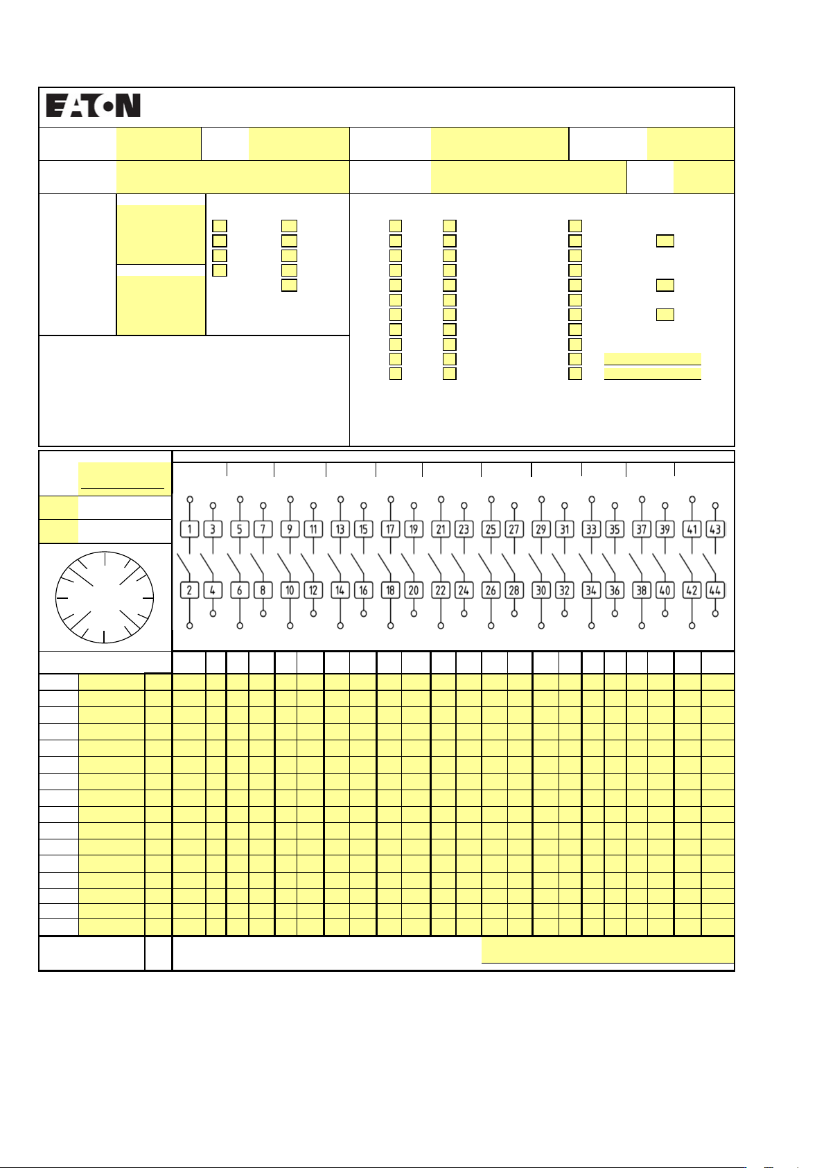
Non standard Cam switches and Switch-disconnectors
Non-standard contact sequence ordering example
Binding document for ordering T cam switch combinations for the first time
Order No.:
123456
Item:
7
Office:
Cologne
Author:
HWS
Customer:
Sample Company
Customer no.:
A4711/2004
Date:
29.2.2004
Quantity:
3
Switching angle: Part no.: Number of contacts: Mounting
form:
□ 30 □ TM □ 1 □ 12 □ E
□ 45 □ T0 □ 2 □ 13 □ EA/SVB □ EA/SVB-SW
Euros/unit: □ 60 □ T3 □ 3 □ 14 □ EZ
□ 90 □ T5B □ 4 □ 15 □ I...
□ T5 □ 5 □ 16 □ I.../SVB □ I.../SVB-SW
□ 6 □ 17 □ IVS
□ 7 □ 18 □ V/SVB □ V/SVB-SW
□ 8 □ 19 □ Z
□ 9 □ 20 □ + ST-0
□ 10 □ 21 □ +___________________
□ 11 □ 22
Max. characters per position
Degrees TM-E TM-EZ TM-IVS T0(3) T5(B)
0.18 5561313
30, 210, 330 8 7 4 8 8
45, 135, 225, 315
65467
60, 120, 240, 300
55357
90, 270 54147
150 44488
Front plate no.
FS______________
Contact units
1234567891011
○ Complete rotation
○ Automatic
spring-return
Inscription
Degrees 1
2
3
4
5
6
7
8
9
10
11
12
13
14
15
16
17
18
19
20
21
22
23
24
25
26
27
28
29
30
31
32
33
34
35
36
37
38
39
40
41
42
43
44
270 1
xxxxxx x
300
315
330 2
x xx x
0
x
30 3
x xx
45
60 4
x
90
Contact only closed in
position 1
Switching with
interruption of contact
Switching without
interruption of contact
Contact closed in positions
1 + 3
Contact closed in positions
1 to 3
Fleeting contact
(only with 60° or 90°)
Late-break contact
Early-make contact
Contact with automatic
spring-return
120
135
150 Key withdrawability for ..S-T0 and SVA-T3:
180 Pos. 1: Key withdrawable
}
In the case of SVA-T3, the unit can
still be switched between
positions 1 and 2 if the key has
been removed..
210 Pos. 2: Key withdrawable
225 Pos. 3: Key withdrawable
240 Pos. 4: Key not withdrawable
Key withdrawable
x
Part no. for repeat orders (to be filled in by factory)
T___________________________________
1
2
3
4
5
6
7
8
9
10
11
12
13
14
15
16
17 19
18
21
20
23
22
25
24
27
26
29
28
31
30
33
32
35
34
37
36
39
38
41
40
43
42
44
330
0
30
300
270
240
225
210
180
150
135
120
90
60
315
45
175EATON P Switch-disconnectors and T Rotary cam switches CA042001EN
Non standard Cam switches and Switch-disconnectors
Switching Type: No. of contacts:
angle:
30 TM 1 12 E
45 T0 2 13 EA/SVB EA/SVB-SW
60 T3 3 14 EZ
90 T5B 4 15 I…
T5 5 16 I…/SVB I…/SVB-SW
6 17 IVS
7 18 V/SVB V/SVB-SW
8 19 XZ
9 20 Z
TM-E
10 21
+
5
11 22
+
8
6
5
5
4
5
FS
1 5 7 11 13 15 19 23 25 27 29 33 35 37 41 43
Degrees Inscription 2 6 8 12 14 16 20 24 26 28 30 34 36 38 42 44
270
300
315
330
0
30
45
60
90
120
135
150
180
210
225
240
T
39
40
56
17
18
21
22
31
9 1078
Item: Office:
Mounting form:
150
5
T0(3)
5
Note:
The number of
possible contacts,
as well as the
possible
combinations with
mounting forms are
shown in the Main
Catalogue.
4
4
13
8
4
7
6
60, 120, 240, 300
0 13
8
7
7
8
3
71
4
4
8
6
30, 210, 330
45, 135, 225, 315
90, 270
5
T5(B)
5
4
Euro/each:
Degrees
Max. characters per switching angle on FS plate
TM-IVS
Binding document for initial orders for T rotary switch combinations
Date:Customer:
TM-EZ
Name:
Customer number:
Order number:
Quantity:
Spring-return
3210
Complete rotation
9
180
5 6 7 13
1
Front plate no.
4
Contact units
11
4
32
3
Key withdrawable
Type for re-ordering (to be filled in by factory)
0
180
270 90
330
30
45
60
315
120
135225
150210
240
300
176
EATON P Switch-disconnectors and T Rotary cam switches CA042001EN