161页面.pdf - 第185页
T ec hnic al data P5 Switch- disconnec tors P5-125 P5-160 P5-250 P5-315 General Standards IE C /EN 6 0 947, VD E 0 66 0, IE C /E N 602 0 4, C SA , U L swi tch-disconnec tor to IEC/EN 609 47 -3 Lifesp an mechanical Operat…
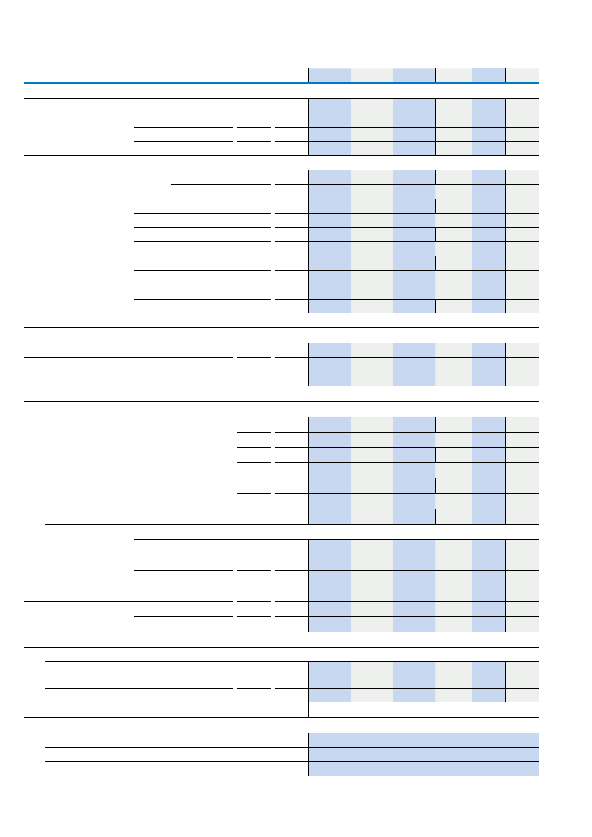
Technical data
P1 and P3 Switch-disconnectors
P1-25 P1-32 P1-40 P3-63 P3-80 P3-100
Switching capacity
AC-23A motor load switch motor load 230 V P kW 7 8.5 11 18.5 30 30
400/415 V P kW 13 15 22 30 50 50
500 V P kW 11 18.5 X 37 65 65
690 V P kW 11 18.5 18.5 30 45 45
DC Voltage
DC-1, load switch L/R = 1 ms Rated operational current I
e
A 25 32 X 63 80 100
Voltage per contact connected in series V 60 60 X 60 60 60
DC-23A, motor load switch
L/R = 15 ms
24 V Rated operational current I
e
A 25 25 X 50 50 50
Contacts Number 1 1 X 1 1 1
48 V Rated operational current I
e
A 25 25 X 50 50 50
Contacts Number 2 2 X 2 2 2
60 V Rated operational current I
e
A 25 25 X 50 50 50
Contacts Number 3 3 X 3 3 3
120 V Rated operational current I
e
A 12 12 X 25 25 25
Contacts Number 3 3 X 3 3 3
Rating data for approved types
UL File No E36332 (Devices for world markets IEC, UL/CSA)
Contacts
Rated operational voltage U
e
V a.c. 600 600 600 600 600 600
Rated operational current I
u
Rated current A 20 30 40 60 80 100
Pilot duty A 600 P 600 A 600 P 600 A 600 P 600 - - -
Switching capacity
AC-3: max, rated power, 40-60 Hz AC motors
3-phase 200 V a.c. HP 5 7½
X
15 15 20
230 V a.c. HP 5 10 X 15 20 25
460 V a.c. HP 10 20
X
40 50 60
575 V a.c. HP 15 25 X 50 60 75
Single-phase 200 V a.c. HP 1½ 2
X
3 5 5
230 V a.c. HP 3 3 X 7½ 10 10
460 V a.c. HP 3 5
X
10 15 15
Short-circuit rating
Standard 600 V a.c. kA 5 5 5 10 10 10
With back-up fuse A 110 110 110 150 150 150
With circuit-breakers Part no. NZMH6 NZMH6 NZMH6 NZMH6 NZMH6 NZMH6
Current setting A 125 125 125 125 125 125
Disconnect in motor circuits 600 V a.c. kA 10 10 10 10 10 -
With back-up fuse Class 50 A/J 50 A/J 50 A/J 100 A 100 A 100 A
Terminal capacity
Terminal capacity
Cu cable Min./ AWG 14 14 14 14 14 14
Max AWG 8 8 8 2 2 2
Tightening torque Max in-lb 14.1 14.1 14.1 26.5 26.5 26.5
H1 11
Auxiliary contacts (1 N/O + 1 N/C)
Pilot duty P 600
Heavy pilot duty A 600
General use 10 A - 600 V AC
184
EATON P Switch-disconnectors and T Rotary cam switches CA042001EN
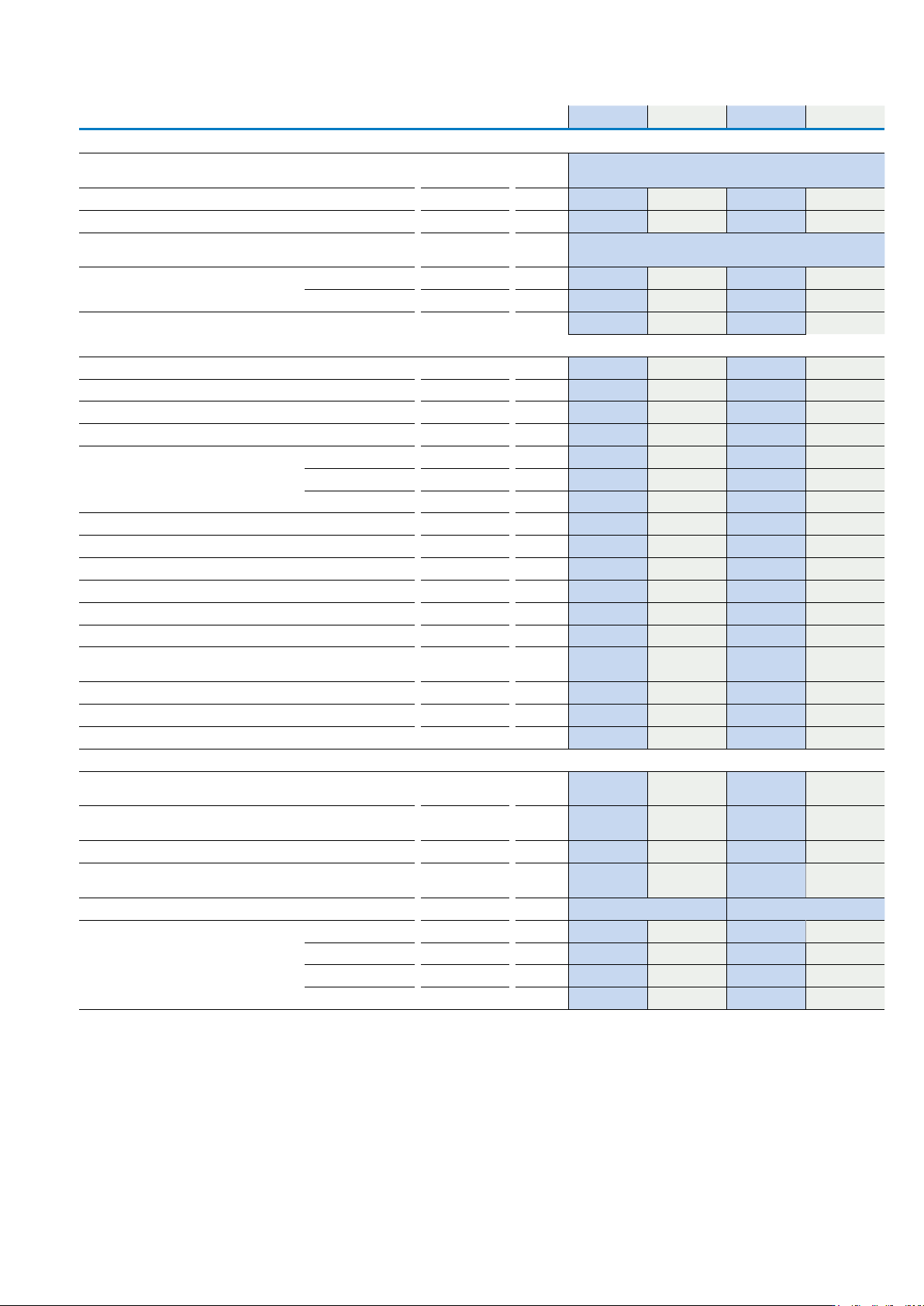
Technical data
P5 Switch-disconnectors
P5-125 P5-160 P5-250 P5-315
General
Standards IEC/EN 60947, VDE 0660, IEC/EN 60204, CSA, UL
switch-disconnector to IEC/EN 60947-3
Lifespan mechanical Operations x 10
6
0.1 0.1 0.08 0.08
Maximum operating frequency Operations/h 50 50 50 50
Climatic proofing Damp heat, constant to IEC 60068-2-78
Damp heat, cyclical to IEC 60068-2-30
Ambient temperature
(for derating information contact buletechnical@eaton.com)
Open
o
C -25 - 50 -25 - 50 -25 - 50 -25 - 50
Enclosed
o
C -25 - 40 -25 -40 -25 - 40 -25 - 40
Mounting position Any Any Any Any
Contacts
Rated operational voltage U
e
V A C 690 690 690 690
Rated impulse withstand voltage U
imp
V A C 8000 8000 8000 8000
Overvoltage category/pollution degree III/3 III/3 III/3 III/3
Rated uninterrupted current I
u
A 125 160 250 315
Load rating with intermittent operation, class 12 AB 60% DF x I
e
1.3 1.3 1.3 1.3
AB 40% DF x I
e
1.6 1.6 1.6 1.6
AB 25% DF x I
e
2 2 2 2
Short-circuit rating Fuse A gG/gL 125 160 250 315
Rated conditional short-circuit current Load side I
q
kA 30 30 30 15
Supply side I
q
kA - - - -
Rated short-time withstand current (1s current) I
cw
A
rms
2500 3000 4600 5800
Isolating characteristics to IEC/EN 60947 V AC ≤ 690 ≤ 690 ≤ 690 ≤ 690
Safe isolation according to EN 61140
Safe isolation to VDE 0106 Part 101 and Part 101 A1 between
the auxiliary contacts and main circuits
VAC 440 440 440 440
Switching angle
o
90 90 90 90
Contacts Number Max. 3 (+N) Max. 3 (+N) Max. 3 (+N) Max. 3 (+N)
Current heat loss per contact at I
e
W 8 10 13 16
Terminal capacity
Solid or stranded mm
2
1 x (10-95)
2 x (10-35)
1 x (10-95)
2 x (10-35)
1 x (16-185)
2 x (16-70)
1 x (10-95)
2 x (10-35)
Copper strip. 1 flat conductor Number of layers x width x
thickness
mm 6 x 9 x 0.8 - 6 x 20 x 1 -
Copper strip. 2 flat conductors mm - 6 x 9 x 0.8 - 6 x 20 x 1
Flexible with ferrule to DIN 46228 mm
2
1 x (16-70)
2 x (16-25)
1 x (16-70)
2 x (16-25)
1 x (25-120)
2 x (25-50)
1 x (25-120)
2 x (25-50)
Terminal screw Hexagon screw 5 Hexagon screw 6
Tightening torque Nm 14 14 16 16
400/415 V P kW 13 15 30 50
500 V P kW 11 18.5 37 65
690 V P kW 11 18.5 30 45
Notes: Main switch characteristics to IEC/EN 60204; positive opening of contacts, operator element positively located on shaft.
Rated uninterrupted current Iu is specified for max cross-section.
For terminal capacity solid, stranded and flexible: Max. 2 cross-section sizes difference admissible when using 2 conductors.
185EATON P Switch-disconnectors and T Rotary cam switches CA042001EN
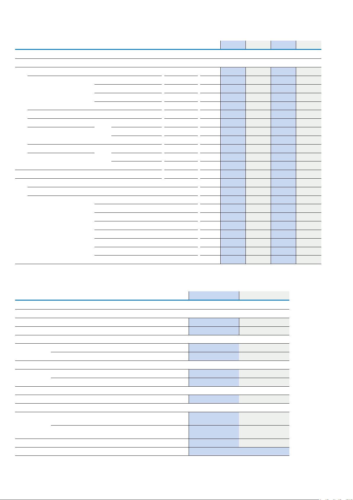
Technical data
P5-125 P5-160 P5-250 P5-315
Switching capacity
AC Voltage
Rated making capacity cos φ = 0.35 A 850 1050 1700 2050
Rated breaking capacity, motor load switch cos
φ = 0.35
230 V A 800 900 1600 1800
400/415 V A 750 850 1380 1650
500 V A 650 850 1250 1550
690 V A 340 340 400 400
Rated operational current 440V, load-break switch AC-21A I
e
A 125 160 250 315
AC-3 motor load switch motor load 230 V P kW 22 30 37 45
400 V P kW 37 45 55 75
690 V P kW 30 37 45 45
AC-23A motor load switch motor load 230 V P kW 30 30 37 55
400 V P kW 45 55 90 110
690 V P kW 37 37 45 45
DC Voltage
DC-1, load switch L/R = 1 ms Rated operational current I
e
A 125 160 250 315
Voltage per contact connected in series V 42 42 42 42
DC-23A, motor load switch
L/R = 15 ms
24 V Rated operational current I
e
A 125 160 250 315
Voltage per contact connected in series Number 3 3 3 3
48 V Rated operational current I
e
A 125 160 250 315
Contacts Number 3 3 3 3
60 V Rated operational current I
e
A 125 160 250 315
Contacts Number 3 3 3 3
120 V Rated operational current I
e
A 125 160 250 315
Contacts Number 3 3 3 3
P5 Switch-disconnectors
Notes: Main switch characteristics to IEC/EN 60204; positive opening of contacts, operator element positively located on shaft. Rated uninterrupted current Iu is
specified for max cross-section.
For terminal capacity solid, stranded and flexible: Max. 2 cross-section sizes difference admissible when using 2 conductors.
HI...-P1(P3)... HI...-P5...
Auxiliary contacts
Standards Control circuit isolator to IEC/EN 60947-5
Rated insulation voltage U
i
V AC 500 500
Rated uninterrupted current I
U
A 10 10
Rated operational current
AC-15 at 230 V I
e
A 6 6
400 V / 415 V I
e
A - -
DC-13
125 V I
e
A 1.1 0.23
250 V I
e
A 0.55 0.1
Short-circuit training
Max fuse A gG/gL 10 10
Terminal capacity
Solid mm
2
1 x 0.75 - 2.5
2 x 0.75 - 1.5
1 x 0.75 - 2.5
2 x 0.75 - 1.5
Flexible with ferrule to DIN 46228 mm
2
1 x 0.5 - 1.5
2 x 0.5 - 1.5
1 x 0.5 - 1.5
2 x 0.5 - 1.5
Tightening torque Nm 0.6 0.8
Control circuit reliability at 24 V d.c., 10 mA H
F
< 10-5, < 1 failure for 100,000 switching operations
186
EATON P Switch-disconnectors and T Rotary cam switches CA042001EN