161页面.pdf - 第190页
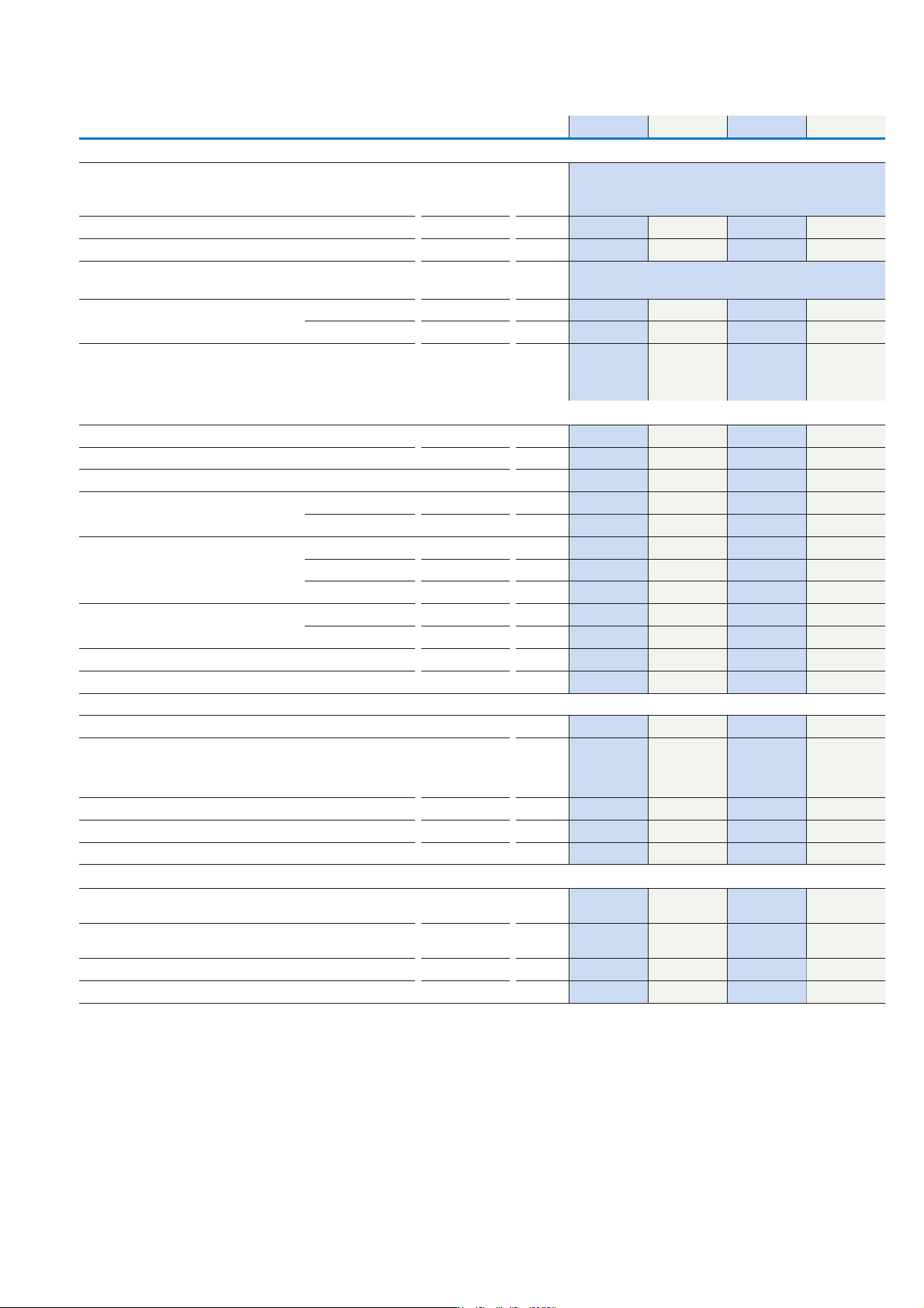
T ec hnic al data T0-... T3-... T5B-... T5-... Switching capacity AC Volt ag e Ra ted ma kin g c ap aci t y c os φ = 0. 35 A 13 0 320 800 960 Ra ted br eak in g c apa ci t y, mo tor lo ad s w it ch c os φ = 0.35 23 0 V A…
Technical data
T0, T3, T5B, T5 Cam switch-disconnectors
T0-... T3-... T5B-... T5-...
General
Standards IEC/EN 60947, VDE 0660, IEC/EN 60204, CSA, UL
switch-disconnector to IEC/EN 60947-3
Load break switch according to IEC/EN60947-3
Lifespan mechanical Operations x 10
6
0.5 0.5 0.5 0.5
Maximum operating frequency Operations/h 3000 3000 3000 3000
Climatic proofing Damp heat. constant to IEC 60068-2-78;
Damp heat, cyclic to IEC 60068-2-30
Ambient temperature
(for derating information contact buletechnical@eaton.com)
Open
o
C -25 -50 -25 -50 -25 -50 -25 -50
Enclosed
o
C -25 -40 -25 -40 -25 -40 -25 -40
Mounting position Any Any Any Any
Mechanical shock resistance to IEC 60068-2-27 Half-sinusoidal shock
to 20 ms
g >15 >15 >15 >15
Contacts
Rated operational voltage U
e
V A C 690 690 690 690
Rated impulse withstand voltage U
imp
V A C 6000 6000 6000 6000
Overvoltage category/pollution degree III/3 III/3 III/3 III/3
Rated uninterrupted current Open I
u
A20 32 63 100
Enclosed I
u
A20 32 63 100
Load rating with intermittent operation, class 12 AB 60% DF x I
e
2222
AB 40% DF x I
e
1.6 1.6 1.6 1.6
AB 25% DF x I
e
1.3 1.3 1.3 1.3
Rated conditional short-circuit current Load side I
q
kA6122
Supply side I
q
kA----
Short-circuit rating Fuse A gG/gL 20 35 80 100
Rated short-time withstand current (1s current) I
cw
A
rms
320 650 1300 1850
Safe isolation according to EN 61140
Between the contacts VAC 440 440 440 440
Switching angle
o
90
60
45
30
90
60
45
30
90
60
45
30
90
60
45
30
Contact units Number Max. 11 Max. 11 Max. 10 Max. 10
Contacts with double-break Max. 22 Max. 22 Max. 20 Max. 20
Current heat loss per contact at I
e
W0.6 1.1 4.5 7.5
Terminal capacity
Solid or stranded mm
2
1 x (1-2.5)
2 x (1-2.5)
1 x (1-2.5)
2 x (1-2.5)
1 x (2.5-35)
2 x (2.5-16)
1 x (2.5-35)
2 x (2.5-16)
Flexible with ferrule to DIN 46228 mm
2
1 x (0.75-2.5)
2 x (0.75-2.5)
1 x (0.75-4)
2 x (0.75-4)
1 x (1.5-25)
2 x (1.5-10)
1 x (1.5-25)
2 x (1.5-10)
Terminal screw M3.5 M4 M6 M6
Tightening torque Nm1244
Notes: The following applies for mechanical shock resistance: T3.../I...>12g.
Applies to T0.../SVB: isolating characteristics to IEC/EN 60947 for rated operational voltage Ue up to 500 V a.c.
The following applies to rated uninterrupted current Iu of contacts: max 95 A with T5-4-8344/I5.
The following applies to solid, stranded and flexible terminal capacities:
T0, , (8)...: If 2 conductors are used, a max difference of 2 cross-section sizes is permissible.
T5(B)-...: If 2 conductors are used, a max difference of 1 cross-section sizes is permissible.
The following applies for part no T8-3-8342/...: switching angle = 90
o
and flat conductor connection = 1 flat conductor.
25 x 5 or 2 flat conductors, 20 x 3
189EATON P Switch-disconnectors and T Rotary cam switches CA042001EN
Technical data
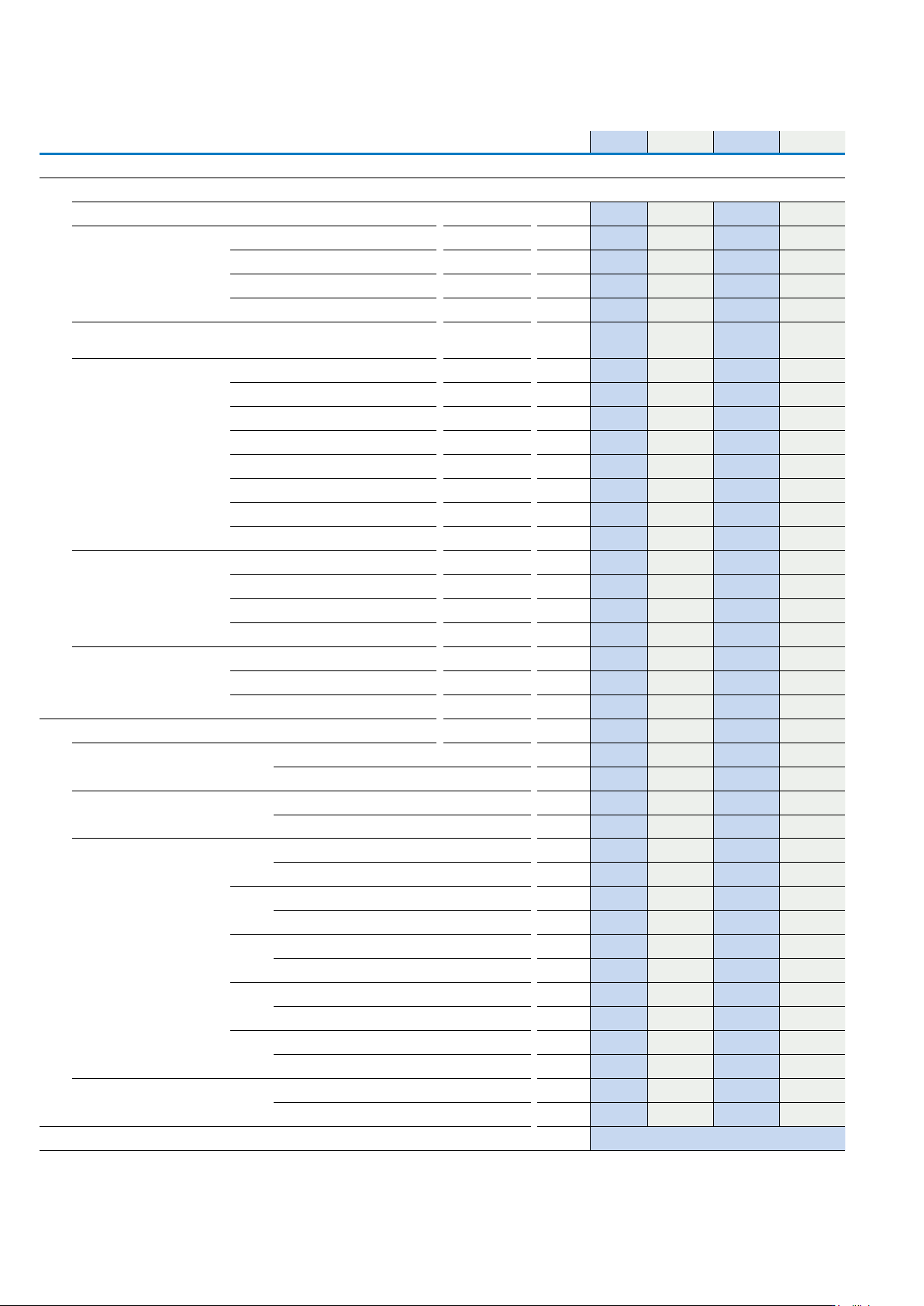
T0-... T3-... T5B-... T5-...
Switching capacity
AC Voltage
Rated making capacity cos φ = 0.35 A 130 320 800 960
Rated breaking capacity, motor
load switch cos φ = 0.35
230 V A 100 260 520 760
400 V A 110 260 600 740
500 V A 80 240 480 590
690 V A 60 170 340 420
Rated operational current,
load-break switch AC-21A
440 V I
e
A 20 32 63 100
Motor rating
Motor load switch AC-3
230 V P kW 3 6.5 15 22
230 V star-delta P kW 4 11 22 30
400/415 V P kW 4 12 22 30
400 V star-delta P kW 5.5 18.5 37 45
500 V P kW 5.5 15 22 37
500 V star-delta P kW 7.5 22 37 55
690 V P kW 4 15 22 30
690 V star-delta P kW 5.5 22 37 45
Motor rating
Motor load switch AC-23A
230 V P kW 3.5 7.5 15 18.5
400/415 V P kW 6.5 13 22 30
500 V P kW 7.5 15 22 37
690 V P kW 6.5 15 22 30
Motor rating
Motor load switch AC-15
230 V P kW 6 10 16 16
400/415 V P kW 4 6 6 6
500 V P kW 2 4 4 4
DC Voltage
DC-1, load switch L/R = 1 ms
Rated operational current I
e
A
10 25 63 80
Voltage per contact connected in series V 60 60 60 60
DC-21A
Rated operational current 240 V A 1 1
240 V contacts Number 1 1
DC-23A, motor load switch
L/R = 15 ms
24 V Rated operational current I
e
A 10 25 50 -
Voltage per contact connected in series Number 1 1 1 -
48 V Rated operational current I
e
A 10 25 50 -
Contacts Number 2 2 2 -
60 V Rated operational current I
e
A 10 25 50 -
Contacts Number 3 3 3 -
120 V Rated operational current I
e
A 5 12 25 -
Contacts Number 3 3 3 -
240 V Rated operational current I
e
A
5 5 20 -
Contacts Number 5 5 6 -
DC-13, control switch L/R =
50 ms
Rated operational current I
e
A
10 20 25 -
Voltage per contact connected in series Number 32 32 24 -
Control circuit reliability at 24 V d.c., 10 mA
Fault probabilty H
F
< 10-5, < 1 failure for 100,000 switching operations
T0, T3, T5B and T5 Cam switch-disconnectors
190
EATON P Switch-disconnectors and T Rotary cam switches CA042001EN
Technical data
T0 T3 T5B
Rating data for approved types
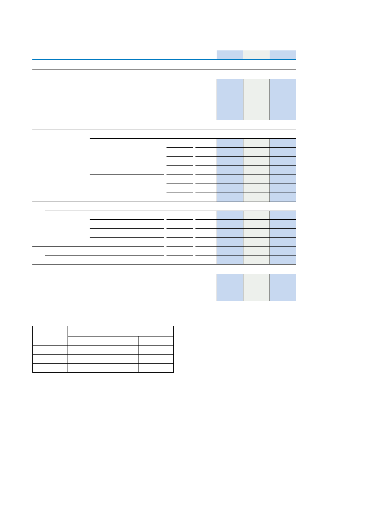
UL File No E36332
Contacts
Rated operational voltage U
e
600 600 600
Rated uninterrupted current I
u
16 25 65
Rated current A 16 25 65
Pilot duty A 600
P 600
A 600
Switching capacity
AC-3, max, rated power, 40-60 Hz AC motors
3-phase 200 V a.c. HP 3 5 15
230 V a.c. HP 3 7½ 15
460 V a.c. HP 10 15 40
575 V a.c. HP 10 15 50
Single-phase 115 V a.c. HP 1 1½ 3
200 V a.c. HP 2 3 7½
230 V a.c. HP 2 3 10
Short-circuit rating
Standard 600 V a.c. kA 5 5 5
With back-up fuse A 50 80 Class J
With circuit-breakers Part No NZMH6 NZMH6 -
Current setting A 50 125 -
Disconnect in motor circuits 600 V a.c. kA 10 10 -
With back-up fuse Class 20 A/J 40 A/J -
Terminal capacity
Cu cable Min AWG 18 14 12
Max MCM 14 10 4
Tightening torque Max in-lb 8.8 17.6 35.3
T0, T3 and T5B Cam switch-disconnectors- Approvals for North America
Notes: Do not use AW extension terminals where UL/CSA approval is required.
UL approved protection types
UL/NEMA 1 UL/NEMA 3R UL/NEMA 12
T0-../E; /Z;/SVB • • -
T3-../E; /Z;/SVB • • -
T5B-../E; /Z;/SVB • • •
Notes: Protection types as defined in NEC (NFPA 70), UL, CSA, NEMA
191EATON P Switch-disconnectors and T Rotary cam switches CA042001EN