161页面.pdf - 第203页
Dime nsio ns 9 88 73 5.5 1 93 216 200 5 76 224 6.4 H- T6-100 118 2 2 68 108 100 R T6-160-6/V/SVB-SW/HI11 - mm 7 130 250 104 4.5 172.8 315 218 9.2 86.5 7 1 130 68 H-T8 19 100 R d2 d1 68 68 a T8-3-8342/V/SVB-(SW)/HI11 - mm…
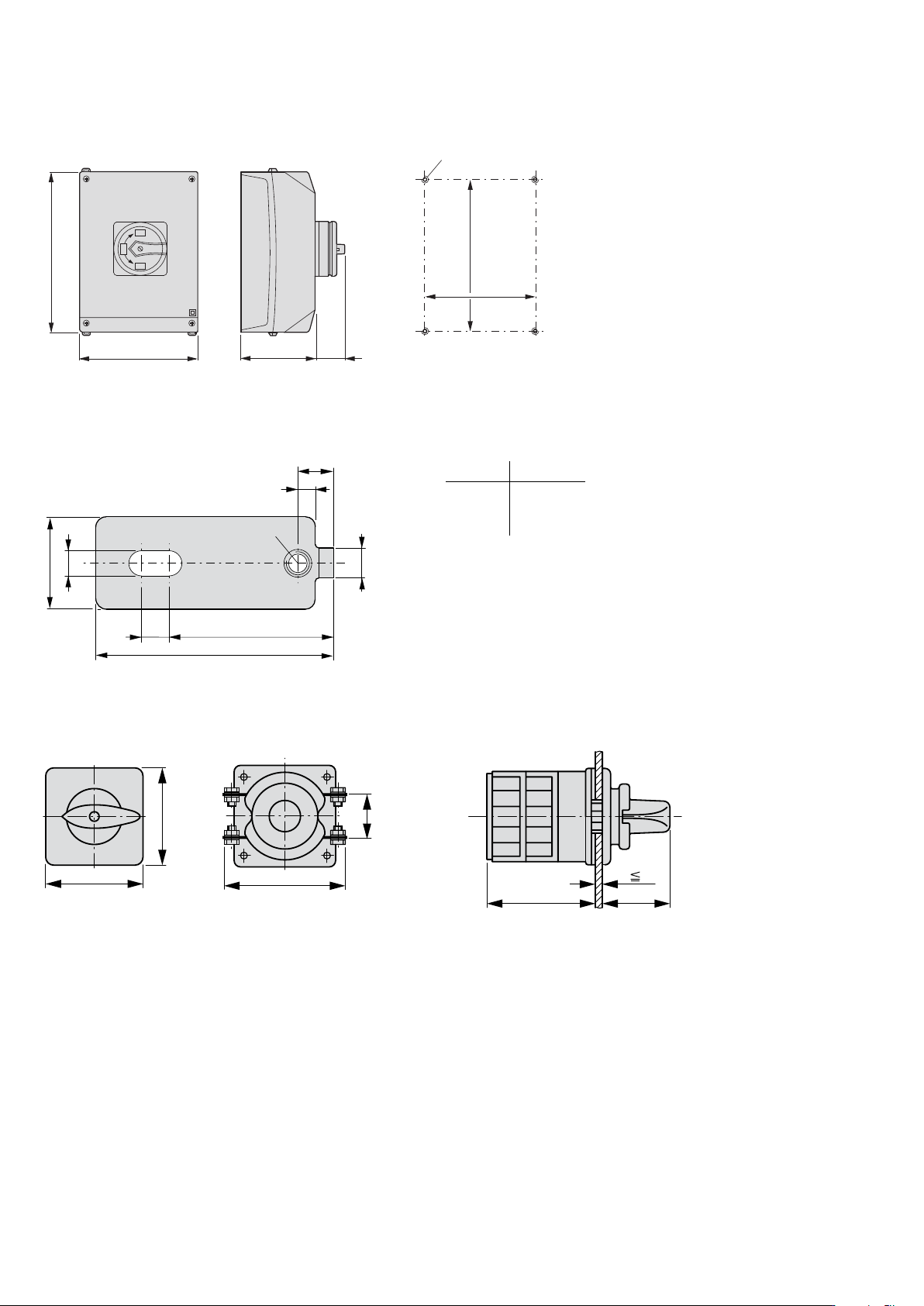
Dimensions
Drilling dimensions
280
200
c22 44
233
182
M5
I
OFF
o
ON
o
OFF
T5 Surface mounting main switches /I5/SVB - mm
Part no. c22
T5(B)-1...
T5(B)-2...
T5(B)-3...
T5(B)-4...
125
125
160
160
Depth of one contact unit: 16.5 mm
Cam switches T5B and T5 have identical designs,
only their contacts are different
20
5.5
6.5
52
36
3.8
M5t = 3
7.8
6
AB-CI-K415 External xing brackets -mm
150
58
5
c2 c30
b2
a2
T6-3-8212/E/HI12 and T8-3-8212/E/HI12 Flush mounting - mm
202
EATON P Switch-disconnectors and T Rotary cam switches CA042001EN
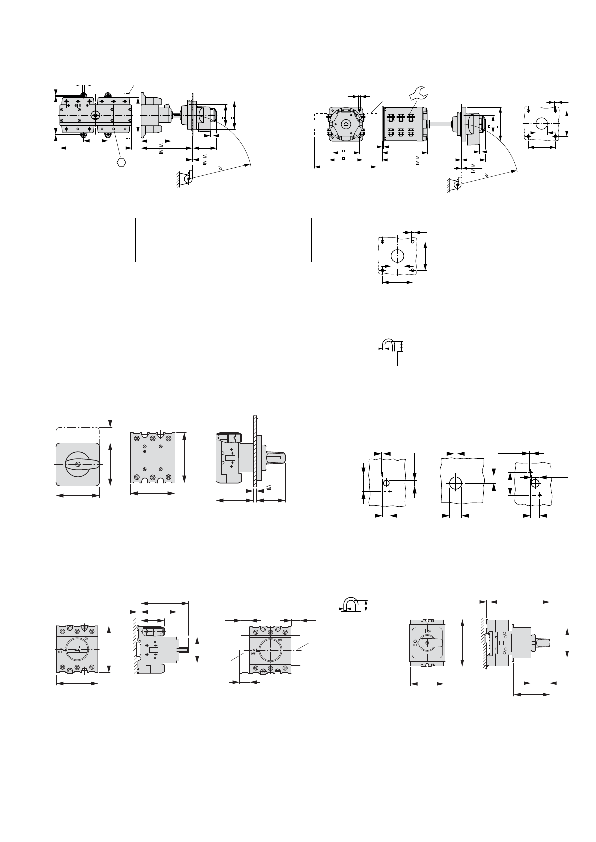
Dimensions
9
88
73
5.5
1
93
216
200
5
76
224
6.4 H-T6-100
118
2
2
68
108
100
R
T6-160-6/V/SVB-SW/HI11 - mm
7
130
250
104
4.5
172.8
315
218
9.2
86.5
7
1
130
68
H-T8
19
100
R
d2
d1
68
68
a
T8-3-8342/V/SVB-(SW)/HI11 - mm
Drilling dimensions
door
T6: 4 M5 x 20
T8: 4 M6 x 20
Ȭ 3 padlocks for T.../SVB
Part no. a2 b2 c2 c30 d1 d2 x1 y1
T6-3-8212/E/HI12
T8-3-8212/E/HI12
T8-3-8342/V/SVB-(SW)/HI11
88
130
–
88
130
–
152
173
44
62
–
Ȳ 26 – 30
Ȳ 22 – 25
Ȳ 26 – 30
Ȳ 6.0
Ȳ 7.0
Ȳ 7.0
68
104
68
68
104
68
d2
d1
x1
y1
d
b
d = 4 – 8 mm
b + d F 47 mm
P Flush mounting/E and Centre mounting /EZ - mm
P.../E P1.../EZ
Drilling dimensions
door
P1-.../E P1-.../EZ P3-.../E
ON
0
I
OFF
a2
b2
b22
b3
a3
L3 L1
T3 T1
L2
T2
1
2
3
4
5
6
5
c2 c21
P1.../EZ = c2 + 5 mm
4.1 – 4.5
3.2
22.3
+0.4
0
12.5
10 – 11
12.2
3.1 – 3.5
30
14
37
12 – 13
P Service distribution board /IVS - mm
P3.../IVS
Ȭ 3 padlocks
P1.../IVS
b3
a4
c22
c23
c3
5
45
N
HI11
L3L2
L1
T3
T2
T1
L3L2
L1
T3
T2
T1
a32
a32
a31
d
b
d = 4 – 8 mm
b + d F 47 mm
49
L1 L2 L3
T1 T2 T3
55
28
b3
45
5
c3
203EATON P Switch-disconnectors and T Rotary cam switches CA042001EN
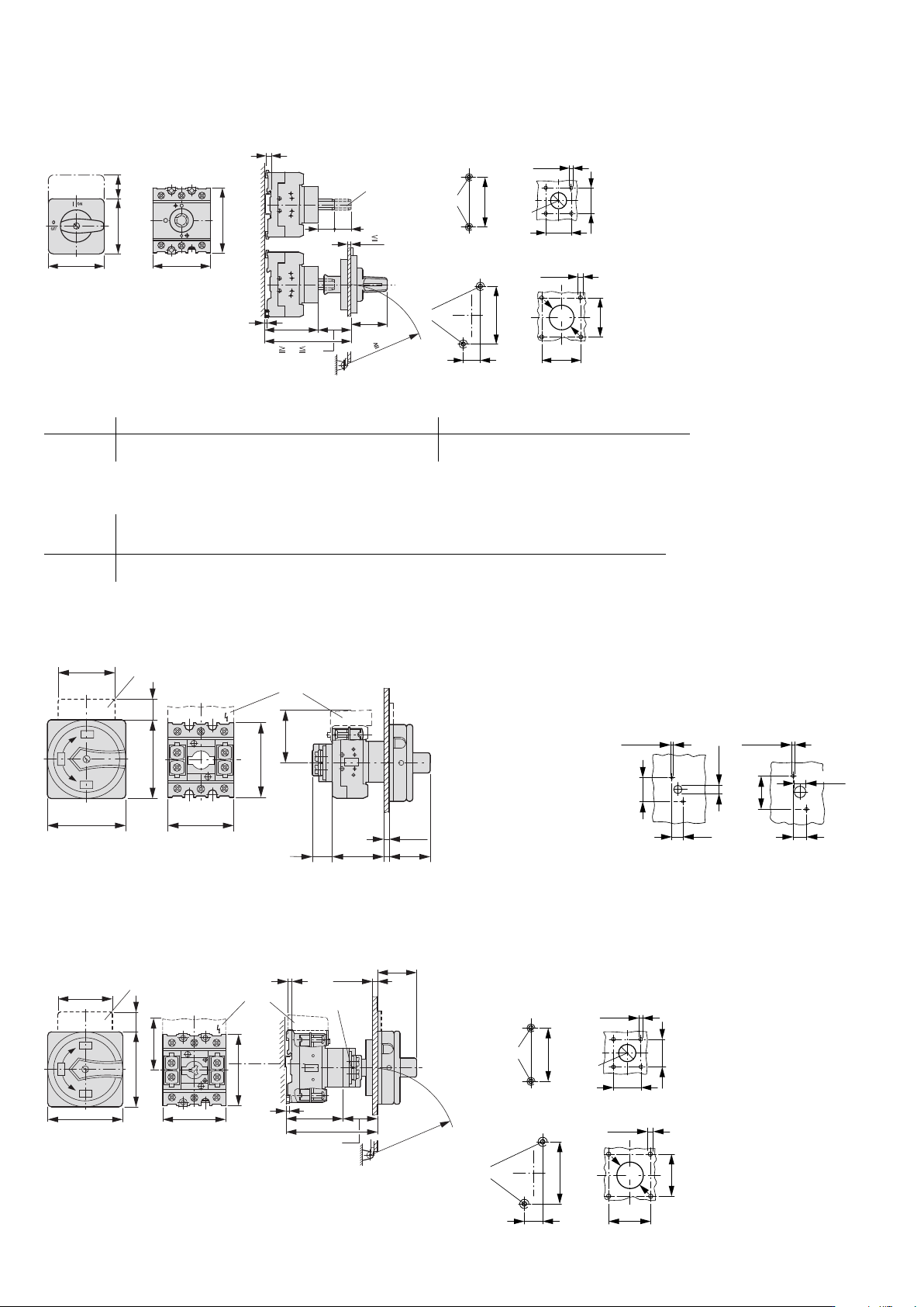
Dimensions
P Rear mounting /Z - mm
ȶ Shaft extension with ZAV-... possible Ȭ 4 x 25 = 100 mm
Drilling dimensions
base
P1.../Z
P3.../Z
Drilling
dimensions
door
a
38,
3
5
a3
5
b22
b2
a2
c21
c25
c20
R
100
c31
c32
b3
54
5 – 5.5
M4
65
36
36
22.3
+0.4
0
M4
75
25
5 – 5.5
48
48
30.5
Part no. a2 a3 a4 a21 a22 a23 a31 a32 a33 b2 b3 b21 b22 b23 b24 b31
P1
P3
48
87
49
72
53.5
71.5
65
87
48
87
87
125
15
18
15
15
83
114
48
87
70
83
65
87
17
27
180
175
32
–
49
60
Part no. c2 c3 c20
ȭ/Ȭ
c20 with
Ȭ 4
ZAV/ZVV
c21 c22 c23 c24 c25 c27 c28 c31 c32 c33
P1
P3
59
59
86
82
96 – 112
103 – 118
212
218
35
37
32
41
65
63
68
81
58
65
35
44
77
90
25
25
25
25
27
29
P Flush mounting main switch /EA/SVB - mm
Drilling dimensions
door
P1...
P3
b3
a3
ON
OFF
b22
c27
c2
25
o
o
OFF
I
1
2
3
4
5
6
N
N
y
y
a22
b21
a21
b31
H-P...
F 5
b
14
4.1 – 4.5
10 – 11
12.2
3.1 – 3.5
30
37
12 – 13
P Rear mounting main switch /V/SVB - mm
ȶ Interlock extension with ZVV-...+ZAV... possible Ȭ 4 x 25 = 100 mm
ȷ Not included as standard
Drilling dimensions
base
P1/V/SVB
P3/V/SVB
Drilling dimensions
door
3
I
ON
OFF
OFF
5
o
o
1
2
3
4
5
6
N
N
a22
a21 a3
c25
c20
c27
b22b21
b31
b3
H-P...
a
F 5
R f 100
f 38, F 54
b
5 – 5.5
M4
65
36
36
22.3
+0.4
0
M4
75
25
5 – 5.5
48
48
30.5
204
EATON P Switch-disconnectors and T Rotary cam switches CA042001EN