161页面.pdf - 第7页
P S w itc h- dis connec to rs - Ov erv ie w Sys tem over view 8 12 13 10 11 14 9 6 10 11 2 3 4 5 7 7 1 1. Neutral conductor 2. P1 rear mounting switch 3. Auxiliary contact 4. P3 rear mounting switch 5. Metal shaft 6. Sha…
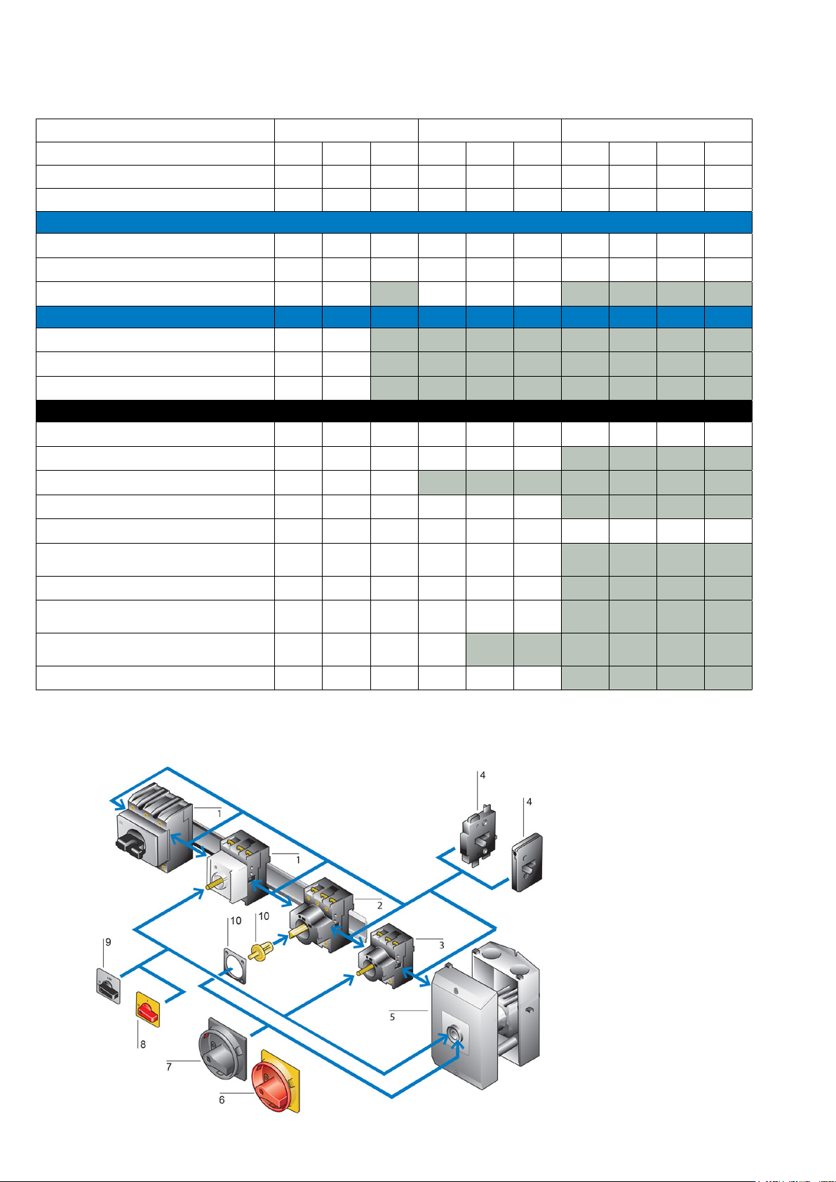
P Switch-disconnectors - Overview
P1 P3 P5
Rated current (Amps) 25 32 40 63 80 100 125 160 250 315
Rated voltage (V a.c.) 690 690 690 690 690 690 690 690 690 690
Max motor rating AC-23A, 400/415 V, 50/60 Hz 13 kW 15 kW 15 kW 37 kW 50 kW 45 kW 55 kW 90 kW 110 kW
Switch-disconnectors type
Main switches maintenance/manual override switches
On-Off switches
Safety switches with warning labels
Switches with interlocks type
With cylinder lock SVA
With padlocking feature SVC
On-Off switch without emergency stop function
Mounting forms
‘E’ Flush mounting
‘EA/SVB’ Flush mounting main switch
‘EZ’ Centre mounting
‘Z’ Rear mounting
‘V/SVB’ Rear mounting main switches
‘M4/SVB’ Rear mounting main switches with extension
shaft
‘IVS’ Service distribution board mounting
‘I’ Surface mounting switch-disconnector fitted in Ci-K
Enclosure
‘MBS’ Surface mounting switch-disconnector fitted in
Ci-K Enclosure, with pre-assembled EMC screen
‘SE’ Surface mounting fitted in steel enclosures
Range overview by switch-disconnectors type and mounting forms
System overview
1. Service distribution board mounting
2. Rear mounting
3. Flush mounting
4. Neutral conductors, auxiliary
contacts
5. Surface mounting
6. Main switch (kit) for use as emer-
gency switching o device
7. Main switch (kit)
8. Thumb grip for use as emergency
switching o device
9. Thumb grip
10. Coupling drive
P1 and P3 Swtich-disconnectors
6
EATON P Switch-disconnectors and T Rotary cam switches CA042001EN
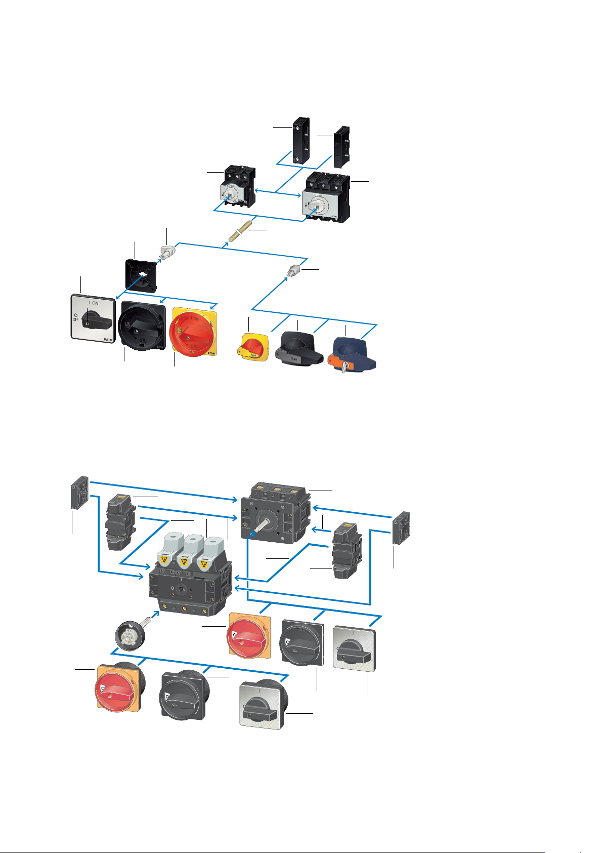
P Switch-disconnectors - Overview
System overview
8
12
13
10
11
14
9
6
10
11
2
3
4
5
7
7
1
1. Neutral conductor
2. P1 rear mounting switch
3. Auxiliary contact
4. P3 rear mounting switch
5. Metal shaft
6. Shaft adaptor
7. Shaft adaptor
8. Centring Adaptor
9. Thumb grip
10. Main switch (kit) black
11. Main switch kit for use as emergency switching o
device (red)
12. Thumb grip kit for use as
emergency switching o device (red)
13. K-Line padlock handles
14. K-Line cylinder lock handles
3
8
2
7
6
5
1
4
8
9
7
6
4
3
9
5
1. Rear mounting
2. Flush mounting
3. Neutral conductors
4. Auxiliary contacts
5. Main switch (kit) for use as
emergency switching o device
6. Main switch (kit)
7. Thumb grip
8. Ground terminal
9. Neutral terminal
P5 Switch-disconnectors
P1 and P3 Switch-disconnectors with metal shaft
7EATON P Switch-disconnectors and T Rotary cam switches CA042001EN
P Switch-disconnectors - Overview
P - Rated
current
(Amps)
/ Mounting form, switch type, handle type / Accesories
P1 25 (P1 only) EA/SVB: Flush mounting, main switch with red/yellow handle
32 (P1 only) EA/SVB-SW: Flush mounting, main switch with black handle
40 (P1 only) E: Flush mounting with black thumb grip and front plate
E-RT: Flush mounting with red thumb grip
P3 63 (P3 only)
100 (P3 only)
P5 125 (P5 only)
160 (P5 only)
250 (P5 only
315 (P5 only)
Flush mounting ‘E’ and ‘EA’
Centre mounting ‘EZ’ P1 switch-disconnectors
P - Rated
current
(Amps)
/ Switch type, mounting form, handle type / Nb of poles
P1 25 (P1 only) EZ: Centre mounting, ON-OFF switch with black thumb grip and front
plate
N: 3-pole +
Neutral
32 (P1 only)
40 (P1 only)
P - Rated
current
(Amps)
/ Mounting
form
Ci-K Enclosure size
(H x W mm)
H / Type of switch, handle / Accesories
P1 25 (P1 only) I : Surface
mounting
in Ci-K
Enclosure
1 (131 x 80 mm)
2(181 x 100 mm)
3 (222 x 120 mm)
4 (240 x 160 mm)
5 (280 x 200 mm)
H: Hard
knockouts
SVB: Main switch with red/yellow handle
32 (P1 only) SVB-SW: Main switch with black handle
40 (P1 only) MBS/SVB: Main switch with red/yellow
handle and pre-assembled EMC screen
P3 63 (P3 only) MBS/SVB-SW: Main switch with black
handle and pre-assembled EMC screen
SVA(S): Panic switch with SVA cylinder lock
SVC(S): Panic switch with SVC padlock
SVA(A): ON-OFF switch with SVA cylinder
lock
S: ON-OFF switch with key operation lock
mechanism ST-0
Surface mounting ‘I’ P1 and P3 switch-disconnectors tted in Ci-K Enclosures
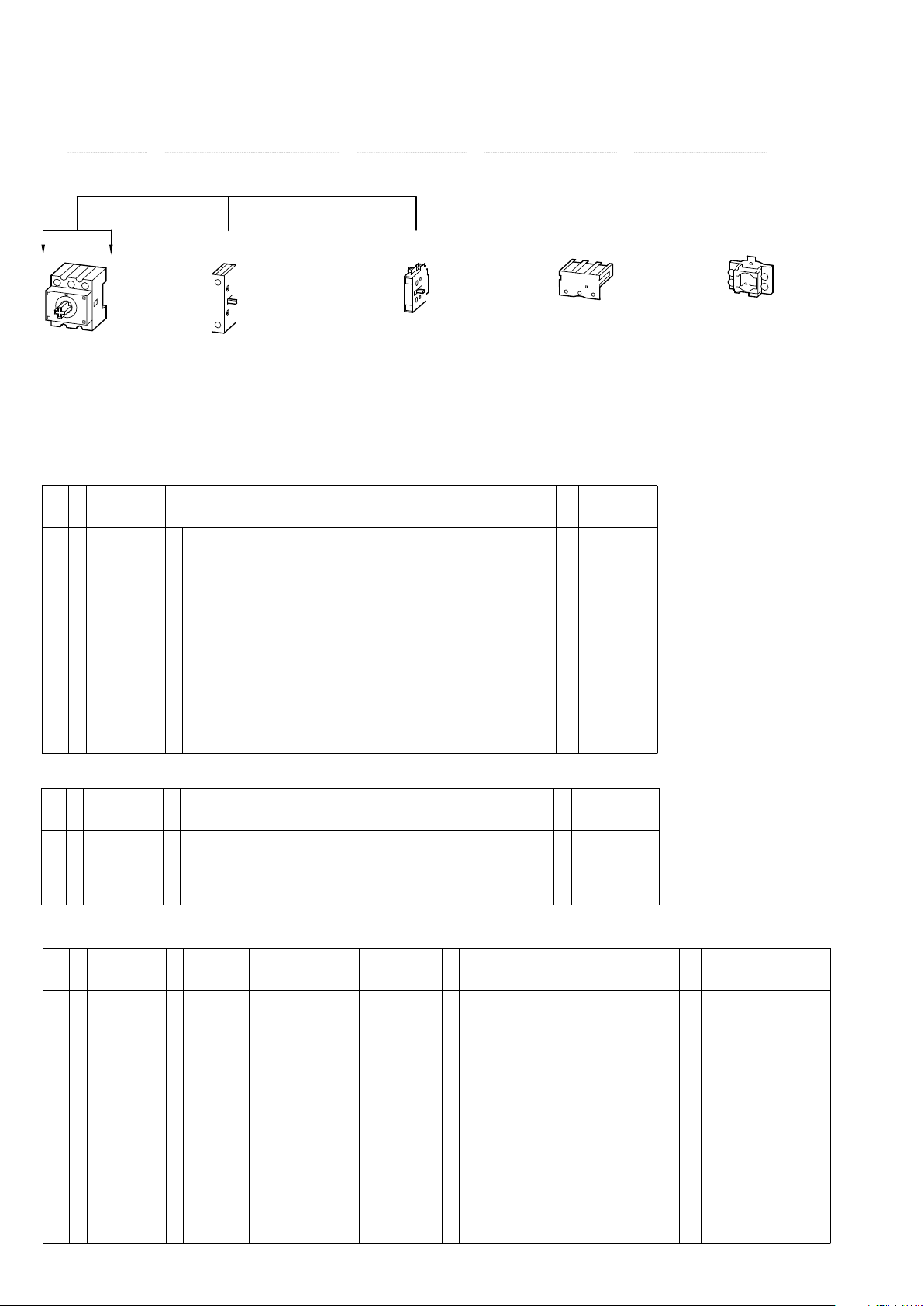
P1 and P3 Key to part numbers
P Switch size - Rated uninterrupted current / Mounting form - Part number suffix / Accessories
P1 or P3 - / - /
H-P...
UV-T0 (P1 only)
UV-P 3
N-P...Z
HI 11-P1/P3Z
N-P...E
HI 11-P1/P3E
3-pole basic unit
.../E or .../Z
Switched neutr
al
Can be fitted left
or right
(for P1.../I: left only)
Auxiliary contact
Can be fitted left
or right
(for P1.../I: left only)
Terminal shroud
can be fitted at
top or bottom
N + PE terminals,
also as cover interlock
on .../Z-switches.
or
or
P1 and P3 add-on function due to modular system
Catalogue number system
8
EATON P Switch-disconnectors and T Rotary cam switches CA042001EN