NPM Calibration Manual-En.pdf - 第13页
NPM Maint en anc e E di ti on 9.4 Head / Plane Compensati on Z Page 9-12 EJM9BE-M B-09M-21 9.4 Head / P lane C ompensati o n Z Thi s procedur e i s co mm on to 12-noz zle, 8-nozzl e, and 2-noz zl e heads. For the dua l c…
NPM
Maintenance Edition
9.3 Plane Compensation XY
EJM9BE-MB-09M-21 Page 9-11
19
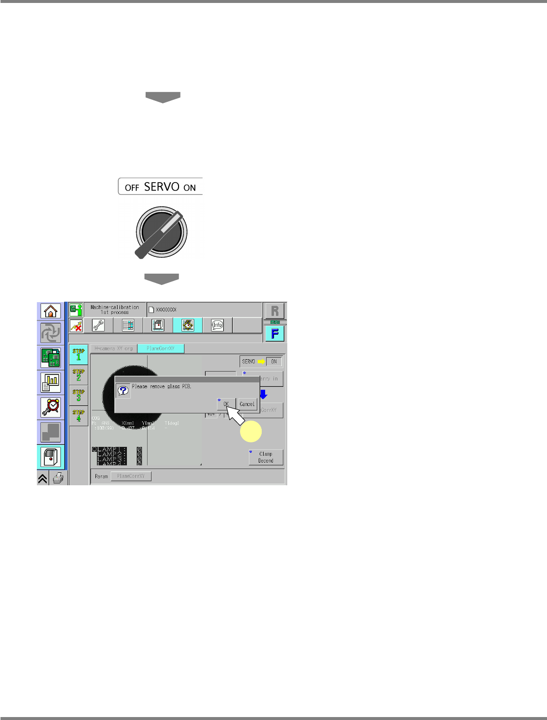
Transfer the plane-compensation jig
to the downstream machine or the
downstream conveyor by hand.
20
Remove the plane-compensation jig.
21
Close the safety cover.
22
Turn ON the servo switch.
23
Press [OK].
•
The screen selected in step 15 is displayed.
UnitCalibAxisSurface-09E00
23
NPM
Maintenance Edition
9.4 Head / Plane Compensation Z
Page 9-12 EJM9BE-MB-09M-21
9.4 Head / Plane Compensation Z
This procedure is common to 12-nozzle, 8-nozzle, and 2-nozzle heads.
For the dual conveyor type, put the conveyor into single lane mode.
( Steps 1 through 7 in “10.5 Single Lane Mode Selection on the Dual Conveyor”.
It is not necessary to attach the board support blocks (for single lane mode).)
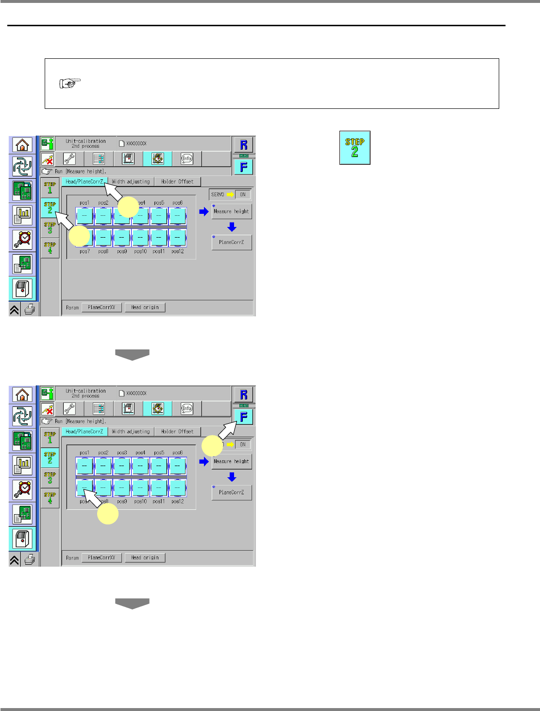
1
Press .
2
Press [Head/PlaneCorrZ].
3
Select a table.
∗
Select the target table for calibration.
4
Select a nozzle position.
∗
Select the target nozzle position for height
measurement.
∗
On the default screen, all the nozzle positions
are selected; basically, all the nozzle positions
should be selected. If, however, there are
unused nozzle positions, only the necessary
nozzle positions should be selected.
UnitCalibAxisSurfaceZ-01E02
1
2
UnitCalibAxisSurfaceZ-01E02
3
4
NPM
Maintenance Edition
9.4 Head / Plane Compensation Z
EJM9BE-MB-09M-21 Page 9-13
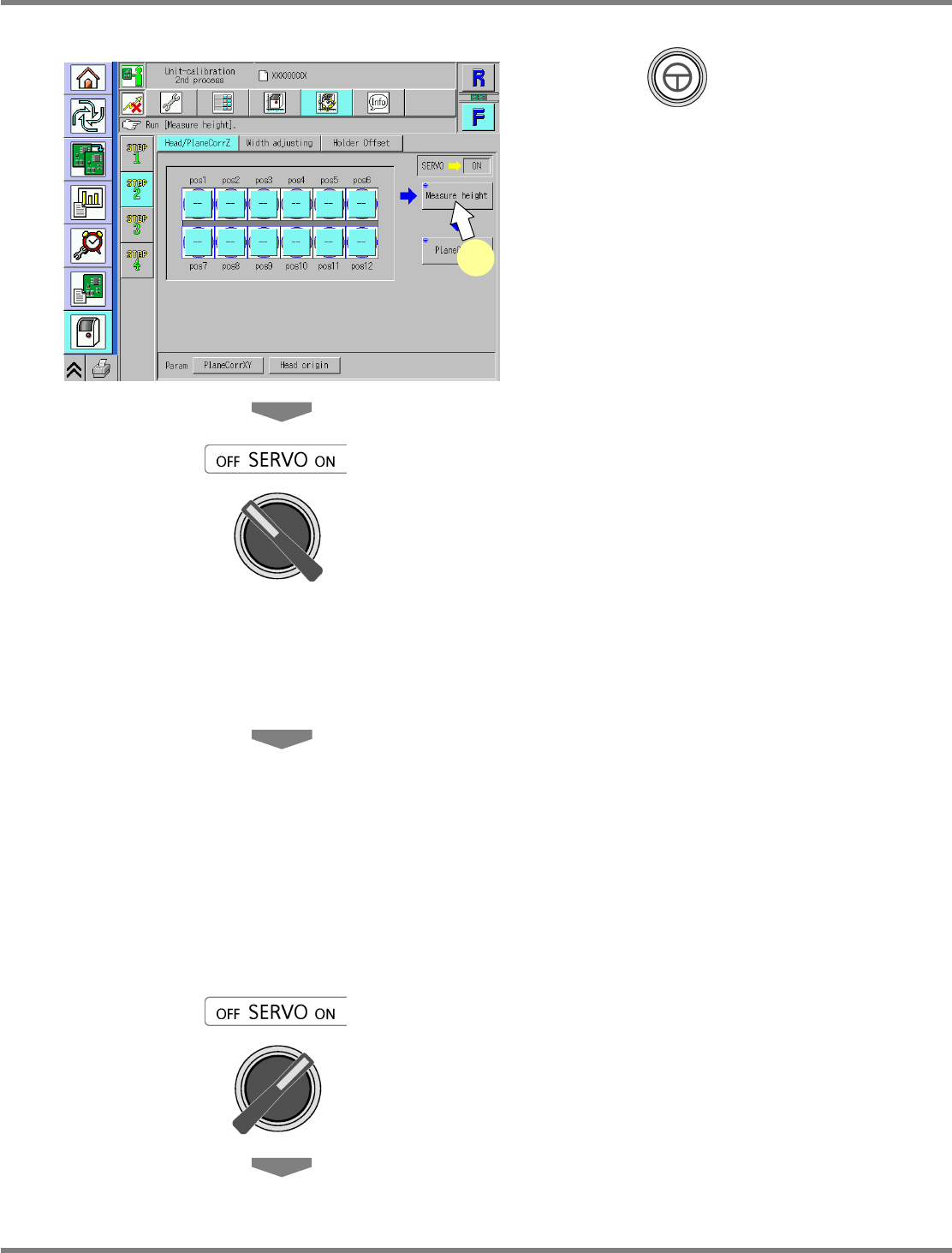
5
Press + [Measure height].
•
The head moves to the working position.
6
Turn OFF the servo switch.
7
Open the safety cover.
8
Attach the nozzles to the nozzle
positions selected in step 4.
12-nozzle head
∗
Attach the 230CS nozzle.
8-nozzle head
∗
Attach the 230C nozzle.
2-nozzle head
∗
Attach the No.1002 nozzle.
9
Close the safety cover.
10
Turn ON the servo switch.
UnitCalibAxisSurfaceZ-01E02
5