NPM Calibration Manual-En.pdf - 第21页
NPM Maint en anc e E di ti on 9.6 Pl ac ement Positi on / Conveyor Page 9-20 EJM9BE-M B-09M-21 9.6 Placement P osition / Conv ey o r Thi s procedur e i s co mm on to 12-noz zle, 8-nozzl e, and 2-noz zl e heads. S ingle…
NPM
Maintenance Edition
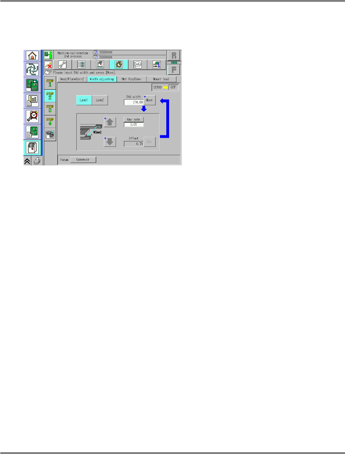
9.5 Width Adjustment
EJM9BE-MB-09M-21 Page 9-19
Dual conveyor type
For the dual conveyor type, select the lanes 1 and 2.
The operating procedure and details are the same as those for the single conveyor.
∗
The reference width is 216 mm.
UnitCalibConveyorWideOrigin-05E00
NPM
Maintenance Edition
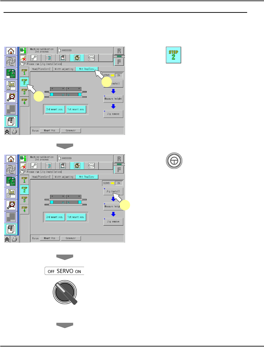
9.6 Placement Position / Conveyor
Page 9-20 EJM9BE-MB-09M-21
9.6 Placement Position / Conveyor
This procedure is common to 12-nozzle, 8-nozzle, and 2-nozzle heads.
Single conveyor type
1
Press .
2
Press [Mnt Pos/Conv].
3
Press + [Jig install].
•
The head moves to the retraction position, the
width-adjustment axis moves to the origin,
and the support blocks ascend.
4
Turn OFF the servo switch.
5
Open the safety cover.
UnitCalibConveyorPCBPos-01E02
1
2
UnitCalibConveyorPCBPos-01E02
3
NPM
Maintenance Edition
9.6 Placement Position / Conveyor
EJM9BE-MB-09M-21 Page 9-21
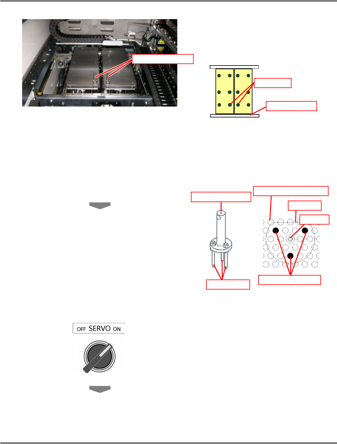
6
Set the support-pin height jigs.
∗
The support-pin height jigs should be set in
such a manner that each of their centers is
positioned in each of the center bolts on the
reference rail side of each support block.
∗
The support-pin height jigs should be set in
such a manner that their respective three
insertion pins are positioned on the support
blocks as shown below.
∗
In addition, the D-cut portion of the
support-pin height jig should face the rear
side.
7
Close the safety cover.
8
Turn ON the servo switch.
Support-pin height jig
Bolt
Reference rail
Support-pin height jig
Insertion pin
Insertion pin position
D-cut
Bolt
Support pin insertion hole