NPM Calibration Manual-En.pdf - 第23页
NPM Maint en anc e E di ti on 9.6 Pl ac ement Positi on / Conveyor Page 9-22 EJM9BE-M B-09M-21 9 Press + [OK]. • T he support bloc ks descend, and t he width- adj ustm ent axi s m oves. 10 Turn OFF the se rvo switch. 11 …
NPM
Maintenance Edition
9.6 Placement Position / Conveyor
EJM9BE-MB-09M-21 Page 9-21
6
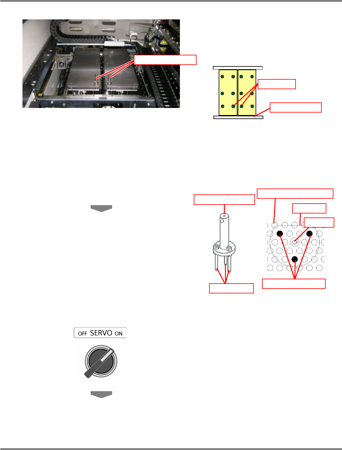
Set the support-pin height jigs.
∗
The support-pin height jigs should be set in
such a manner that each of their centers is
positioned in each of the center bolts on the
reference rail side of each support block.
∗
The support-pin height jigs should be set in
such a manner that their respective three
insertion pins are positioned on the support
blocks as shown below.
∗
In addition, the D-cut portion of the
support-pin height jig should face the rear
side.
7
Close the safety cover.
8
Turn ON the servo switch.
Support-pin height jig
Bolt
Reference rail
Support-pin height jig
Insertion pin
Insertion pin position
D-cut
Bolt
Support pin insertion hole
NPM
Maintenance Edition
9.6 Placement Position / Conveyor
Page 9-22 EJM9BE-MB-09M-21
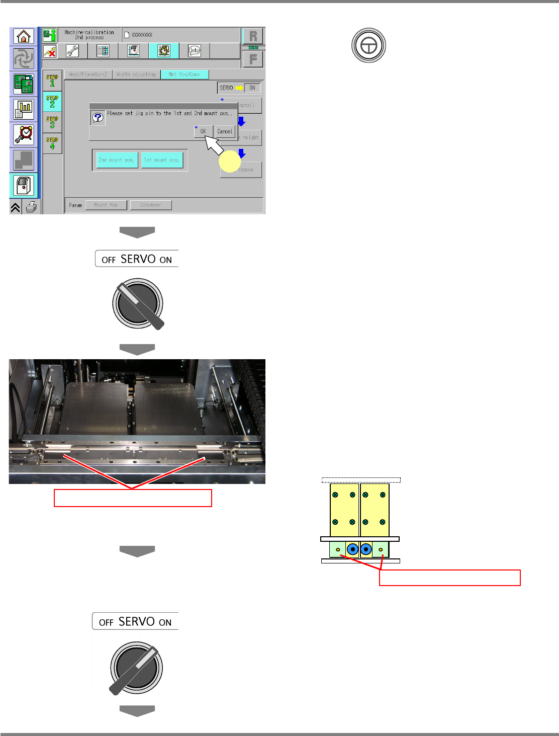
9
Press + [OK].
•
The support blocks descend, and the
width-adjustment axis moves.
10
Turn OFF the servo switch.
11
Open the safety cover.
12
Set the placement-height teaching
jigs.
∗
The placement-height teaching jig for the right
1st placement position should be set with its
right end fit to the right end of the PCB clamp.
The placement-height teaching jig for the left
2nd placement position should be set with its
left end fit to the left end of the PCB clamp.
13
Close the safety cover.
14
Turn ON the servo switch.
Placement-height teaching jig
Placement-height teaching jig
UnitCalibConveyorPCBPos-02E01
9
NPM
Maintenance Edition
9.6 Placement Position / Conveyor
EJM9BE-MB-09M-21 Page 9-23
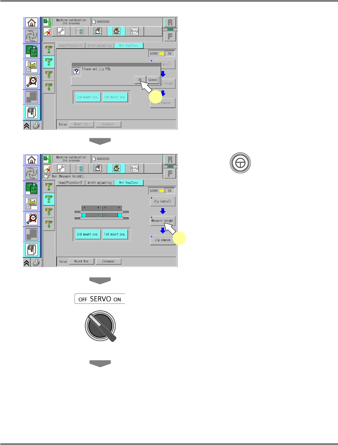
15
Press [OK].
16
Press + [Measure height].
•
The head moves to the working position.
17
Turn OFF the servo switch.
18
Open the safety cover.
UnitCalibConveyorPCBPos-03E01
15
UnitCalibConveyorPCBPos-04E01
16