NPM Calibration Manual-En.pdf - 第3页
NPM Maint en anc e E di ti on 9.1 NPM Calibrati on It ems and Pr ocedures Page 9-2 EJM9BE-M B-09M-21 9.1 NPM Cali bration Item s and Procedures NOTICE Observe the fo ll ow i ng w hen perform ing calibr ation. • T urn ON …

NPM
Maintenance Edition
EJM9BE-MB-09M-21 Page 9-1
9. Calibration
This chapter describes the calibration procedures.
Calibration refers to the adjustment for setting the parameters in order to correct the
individual differences from machine to machine.
Perform calibration in the following cases:
After the machine has been relocated
After the replacement of unit(s)
If the floor level has been changed
Calibration requires the following time:
12-nozzle head (front/rear) specification: About 60 minutes
2-nozzle head (front/rear) and tray feeder specification: About 60 minutes
NPM
Maintenance Edition
9.1 NPM Calibration Items and Procedures
Page 9-2 EJM9BE-MB-09M-21
9.1 NPM Calibration Items and Procedures
NOTICE
Observe the following when performing calibration.
•
Turn ON the main power switch of the machine at least 1 hour before starting
calibration.
•
Do not perform warm-up operation before starting calibration.
•
After the machine has been stopped during production or warm-up operation, wait
more than 3 hours before starting calibration.
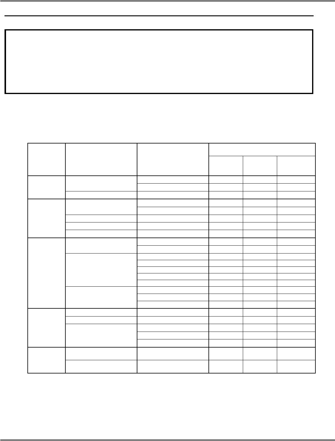
9.1.1 Calibration Items
The table below shows the calibration items and the items to be performed in response to the changes in
machine conditions (relocation, unit replacement, etc.).
Changes in machine condition and
calibrations to be performed
STEP Menu Sub-menu
Relocation,
change in
floor level
Addition of
3D sensor
∗
2
Replacement
of head
∗
2
Camera angle c
−
−
H-camera XY org
XY Origin Camera scale
c
−
−
STEP 1
PlaneCorrXY
PlaneCorrXY
∗
1
c
−
−
Measure height c
−
c
Head/PlaneCorrZ
PlaneCorrZ
∗
1
c
−
−
Width adjusting Std width move
−
−
−
Mnt Pos/Conv Measure height
−
−
−
STEP 2
Mount load Load meas(F1)/(F2)
−
−
−
H
θ
axis origin
−
−
−
L-camera
Camera offset
−
−
−
ScanPos. c
c
c
Changer H c
c
c
HCMR Light c
c
c
PCMR Light c
c
c
Jig station
HeadOffset
c
c
c
Height Scale
(
c
)
c
(
c
)
ScanPos.
(
c
)
c
(
c
)
STEP 3
3DCamera (Option)
HeadOffset
(
c
)
c
(
c
)
Height offset Pickup c
−
−
VerticalCamera (Option)
Camera offset
(
c
)
−
(
c
)
Pickup
(
c
)
−
−
Pickup pos. 1
(
c
)
−
−
STEP 4
Tray
Pickup pos. 2
(
c
)
−
−
Placement accuracy
Reflection
c
c
c
Accuracy
Verification
Placement accuracy
Verification
c
c
c
c
: To be performed
(
c
): To be performed only for the machines with that option
∗
1: When the machine is equipped with the dual conveyor, it is necessary to change to the
single lane mode.
∗
2: Perform calibration only for the table where the unit has been replaced.
NPM
Maintenance Edition
9.1 NPM Calibration Items and Procedures
EJM9BE-MB-09M-21 Page 9-3
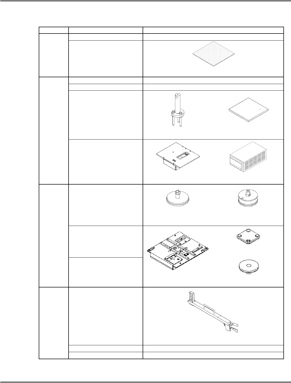
9.1.2 Jigs to be Used for Calibration
The table below lists the types of jigs to be used for calibration.
STEP Menu Jigs used
H-camera XY org
−
STEP 1
PlaneCorrXY
Plane-compensation jig
(N610064253AA)
Head/PlaneCorrZ
−
Width adjusting
−
Mnt Pos/Conv
Support-pin height jig
(N610084259AA)
Placement-height teaching jig
(N610003319AA)
STEP 2
Mount load
Load measuring jig
(N610084605AA)
Load cell meter
(N610093887AB)
For 12-/8-nozzle head
(N610071657AA)
For 2-nozzle head
(N610003301AA)
L-camera
Line camera jigs
Jig station
Jig component
(N610102559AA)
STEP 3
3DCamera (Option)
Jig station
(N610087861AA)
Light luminosity jig
(N610071689AA)
Height offset
Pickup-position-height teaching jig
(N610003318AA)
VerticalCamera (Option)
−
STEP 4
Tray
−