NPM Calibration Manual-En.pdf - 第31页
NPM Maint en anc e E di ti on 9.6 Pl ac ement Positi on / Conveyor Page 9-30 EJM9BE-M B-09M-21 The f oll owing explai ns the dual l ane mode. 1 Press . 2 Press [Mnt P os/Conv]. 3 Press + [Jig install]. The support bl ock…
NPM
Maintenance Edition
9.6 Placement Position / Conveyor
EJM9BE-MB-09M-21 Page 9-29
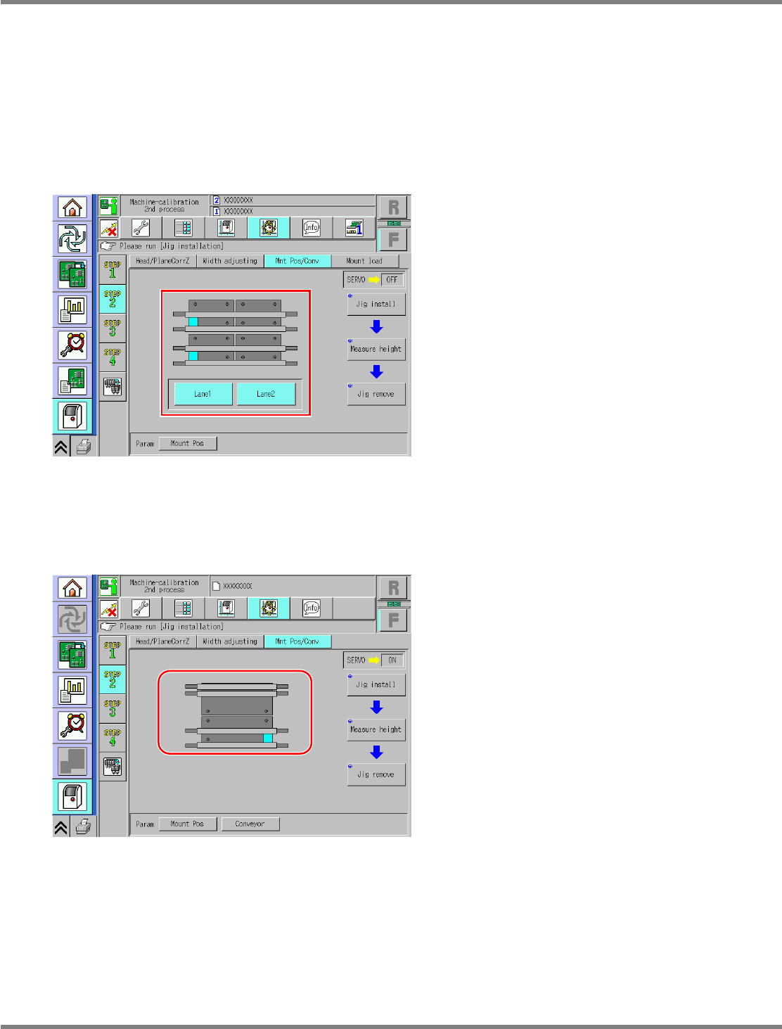
Dual conveyor type
For the dual conveyor type, only the placement height is measured. The operation screen varies
according to whether the conveyor mode is dual lane mode or single lane mode.
The operation screen switches according to the conveyor mode automatically.
In dual lane mode, you can select the lane 1 or the lane 2, allowing calibration of each lane.
For single lane mode, only the lane 1 is targeted.
The operation is the same.
A) For dual lane mode
B) For single lane mode
UnitCalibConveyorPCBPos-15E00
UnitCalibConveyorPCBPos-016E01
NPM
Maintenance Edition
9.6 Placement Position / Conveyor
Page 9-30 EJM9BE-MB-09M-21
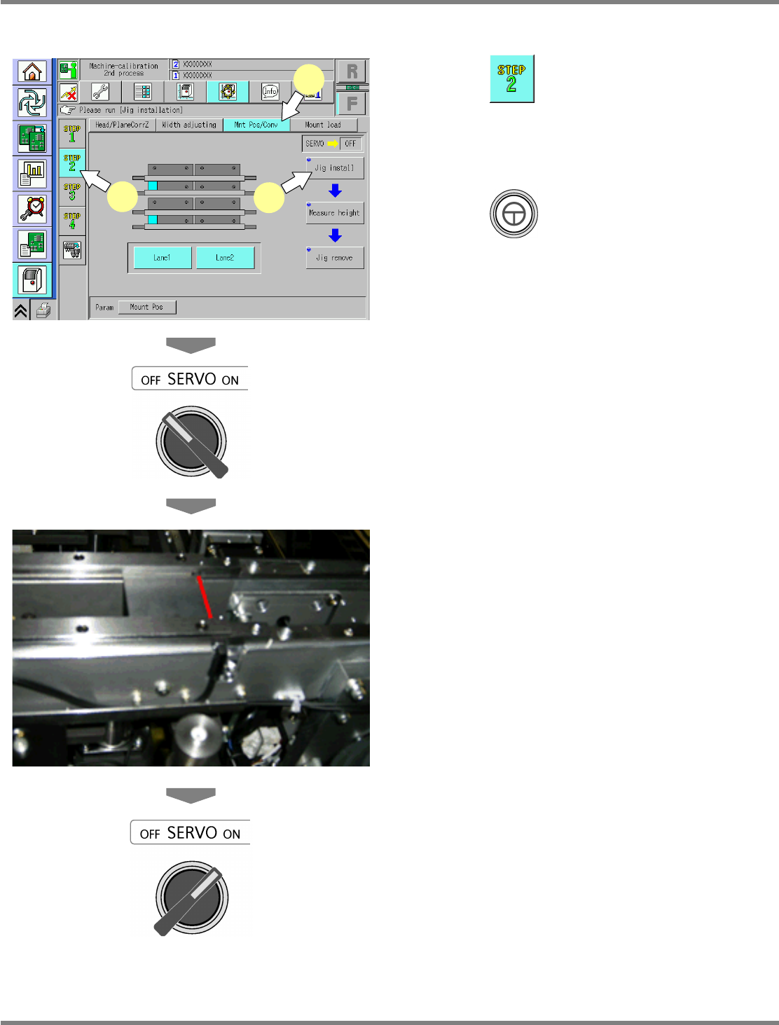
The following explains the dual lane mode.
1
Press .
2
Press [Mnt Pos/Conv].
3
Press + [Jig install].
The support blocks descend, and the
width-adjustment axis moves.
4
Turn OFF the servo switch.
5
Open the safety cover.
6
Set the placement-height teaching
jigs.
•
It should be set with its right end fit to the right
end of the PCB clamp.
∗
Set both the lane 1 and the lane 2 to the right
end.
7
Close the safety cover.
8
Turn ON the servo switch.
The subsequent steps are the same as step 15
and later for the single conveyor type.
∗
The screen for removing the support-pin
height jigs will not be displayed. (Because it is
not used in dual lane mode.)
UnitCalibConveyorPCBPos-15E00
1
2
3
NPM
Maintenance Edition
9.7 Placement Load
EJM9BE-MB-09M-21 Page 9-31
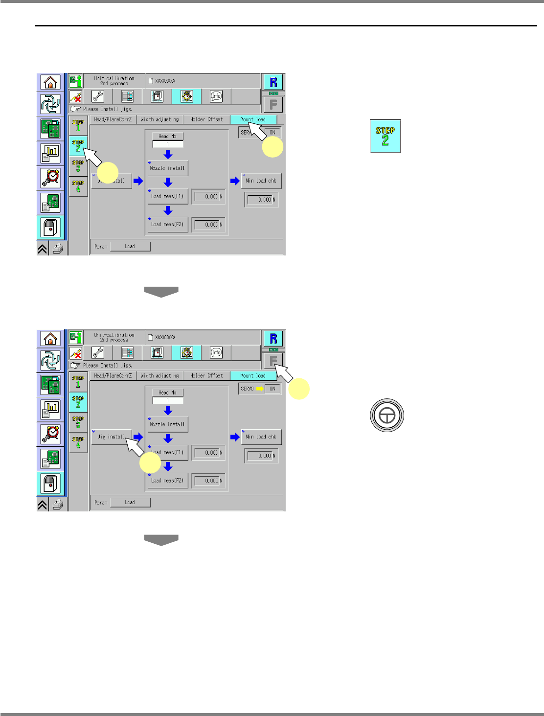
9.7 Placement Load
This procedure is exclusive to the 2-nozzle head.
1
Adjust the conveyor width to 120 mm.
2
Press .
3
Press [Mount load].
4
Select a table.
∗
Select the target table for calibration.
5
Press + [Jig install].
UnitCalibHeadLoad-01E02
2
3
UnitCalibHeadLoad-01E02
5
4