NPM Calibration Manual-En.pdf - 第44页
NPM Maint en anc e E di ti on 9.7 Pl ac ement Load EJM9BE-M B-09M-21 Page 9-43 Set t he load measuri ng ji g so that it s r i ght end fit s to the ri ght end of the PCB cl amp. Then, c onnect the power cabl e t o any por…
NPM
Maintenance Edition
9.7 Placement Load
Page 9-42 EJM9BE-MB-09M-21
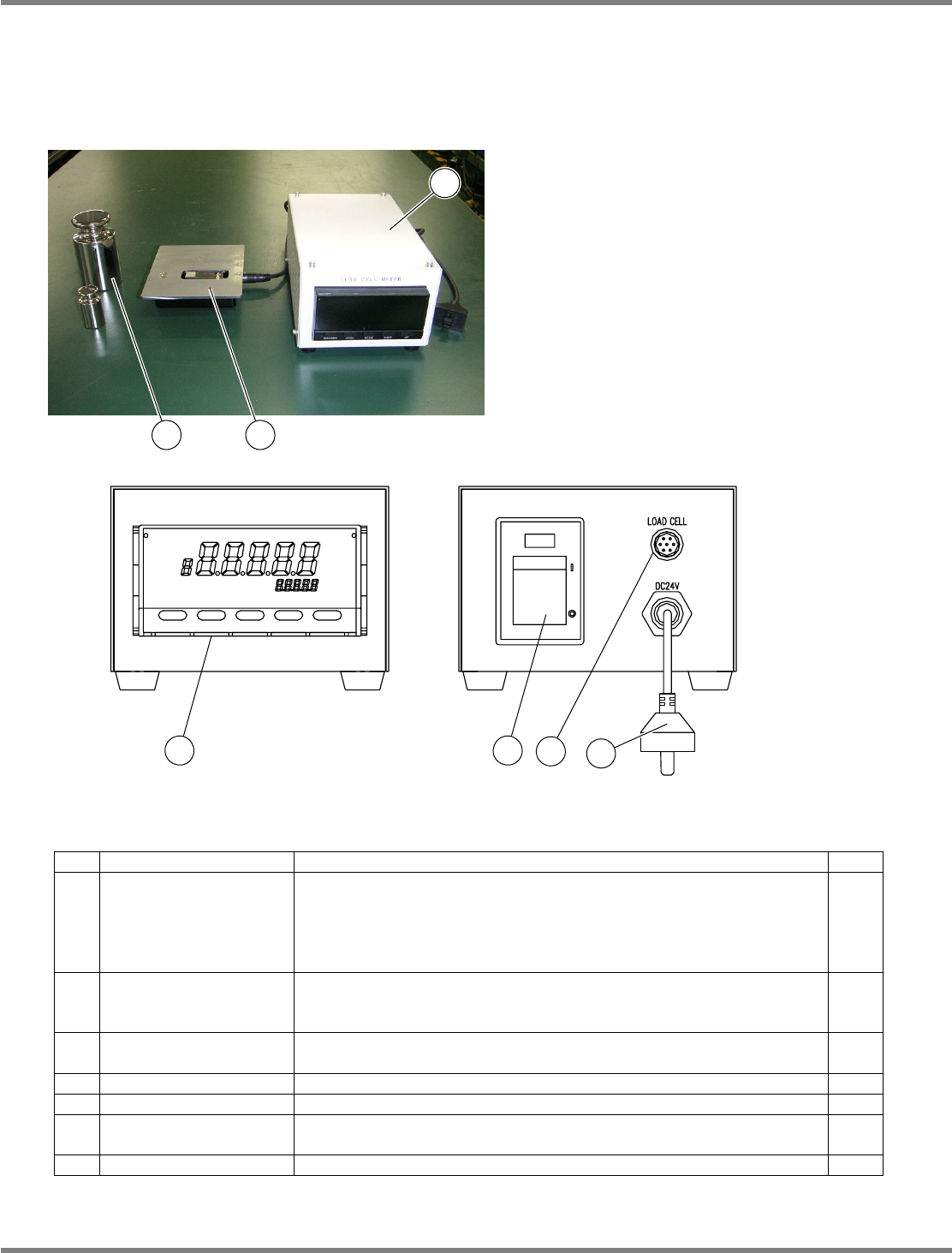
Load measuring jig (Option)
Initial settings
Normally, the initial settings are not necessary because factory-configured.
Jig configuration
No. Unit name Function Qty
1 Load cell meter
Used for calibration to control the head load after head replacement.
Exclusive to the 2-nozzle head.
Power rating: 24 VDC, 7 VA
Mass: 1.2
kg
, overall dimensions: 120 mm (W)
×
80 mm (H)
×
190
mm (D)
1
2 Load cell
Sensor for load measurement. To be used by connecting with the
load cell meter (1).
Mass: 600
g
1
3 Weights
Used to calibrate the load cell meter (1).
Mass: 100
g
/ 1
kg
1
each
4 Display Indicates the load value.
---
5 Power switch Turns ON/OFF the power to the load cell meter.
---
6
Sensor cable
connector
Connects to the load cell with the included cable.
---
7 Power cable Connects to the changing truck to supply power.
---
3
2
1
4 5
6
7
NPM
Maintenance Edition
9.7 Placement Load
EJM9BE-MB-09M-21 Page 9-43
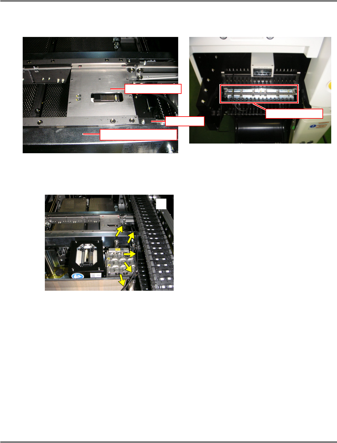
Set the load measuring jig so that its right end fits to the right end of the PCB clamp. Then, connect the
power cable to any port of the power supply unit of the changing truck.
The jig should be pressed against the rail’s reference side in response to the settings of PCB flow
direction and front/rear reference and set with its end fits to the end of the PCB clamp in the horizontal
direction. Route the wires so that they will not interfere with the head, as shown in the photo
.
EJM4A-042P
Power supply unit
Rail (on the reference side)
Load measuring jig
Stopper

NPM
Maintenance Edition
9.7 Placement Load
Page 9-44 EJM9BE-MB-09M-21
Indicator operations
MAX/MIN :
Used to toggle a display from the current, MAX, and MIN values and reset
them.
LEVEL : Used to select levels.
MODE : Used to select parameters to display.
SHIFT : Used to change the set value of parameter, and shift the digit of set value.
UP : Used to change the set value, and input/cancel forced zero.
∗
The following pages describe the setting procedures for the load measuring jig.
EJM4A-414E