NPM Calibration Manual-En.pdf - 第45页
NPM Maint en anc e E di ti on 9.7 Pl ac ement Load Page 9-44 EJM9BE-M B-09M-21 Indicator operat i ons MAX/MIN : Used to toggl e a displ ay fr om the current , MAX, and MIN v a l ues and reset them . LEVEL : U sed to se…
NPM
Maintenance Edition
9.7 Placement Load
EJM9BE-MB-09M-21 Page 9-43
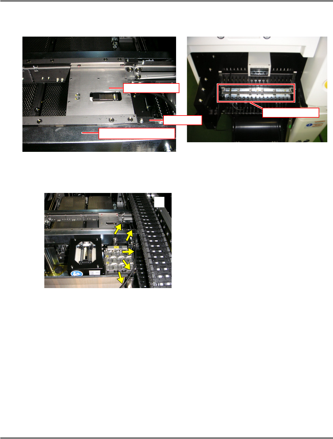
Set the load measuring jig so that its right end fits to the right end of the PCB clamp. Then, connect the
power cable to any port of the power supply unit of the changing truck.
The jig should be pressed against the rail’s reference side in response to the settings of PCB flow
direction and front/rear reference and set with its end fits to the end of the PCB clamp in the horizontal
direction. Route the wires so that they will not interfere with the head, as shown in the photo
.
EJM4A-042P
Power supply unit
Rail (on the reference side)
Load measuring jig
Stopper

NPM
Maintenance Edition
9.7 Placement Load
Page 9-44 EJM9BE-MB-09M-21
Indicator operations
MAX/MIN :
Used to toggle a display from the current, MAX, and MIN values and reset
them.
LEVEL : Used to select levels.
MODE : Used to select parameters to display.
SHIFT : Used to change the set value of parameter, and shift the digit of set value.
UP : Used to change the set value, and input/cancel forced zero.
∗
The following pages describe the setting procedures for the load measuring jig.
EJM4A-414E
NPM
Maintenance Edition
9.7 Placement Load
EJM9BE-MB-09M-21 Page 9-45
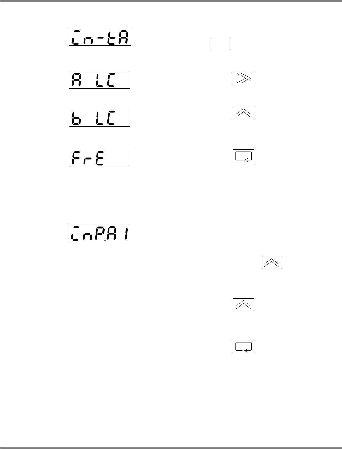
1. Setting the input range
1
Turn on the power, and hold down
for three seconds or more.
2
Press once to blink ‘A LC.’
3
Press several times until ‘b
LC’ appears.
4
Press to accept.
2. Setting the input value 1
1
Set a screen display to ‘inP.A1.’
2
Place a 100
g
weight onto the load
cell, and press once.
•
The screen display blinks.
3
Press again.
•
Teaching is complete.
4
Press to accept.
EJM4A-415E
4H4C-442E
4H4C-443E
4H4C-441E
EJM4A-416E