NPM Calibration Manual-En.pdf - 第58页
NPM Maint en anc e E di ti on 9.9 Ji g Stati on EJM9BE-M B-09M-21 Page 9-57 9.9 Jig Station No. Uni t name Func tion Qt y 1 Ji g station Used f or cali br ation o f the head param e ter s after head replacem ent. Comm on…
NPM
Maintenance Edition
9.8 Line Camera
Page 9-56 EJM9BE-MB-09M-21
32
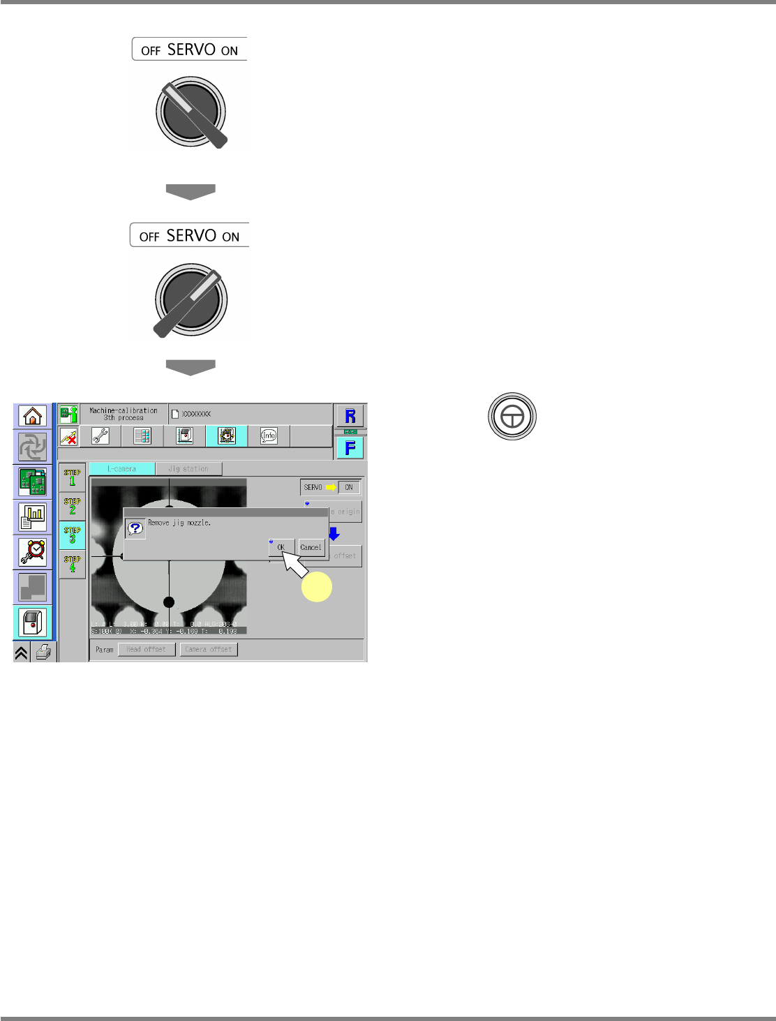
Turn OFF the servo switch.
33
Open the safety cover.
34
Remove the jig nozzle.
35
Close the safety cover.
36
Turn ON the servo switch.
37
Press + [OK].
•
After the head moves to the origin position,
the screen selected in step 33 is displayed.
UnitCalibLineCamera-12E00
37
NPM
Maintenance Edition
9.9 Jig Station
EJM9BE-MB-09M-21 Page 9-57
9.9 Jig Station
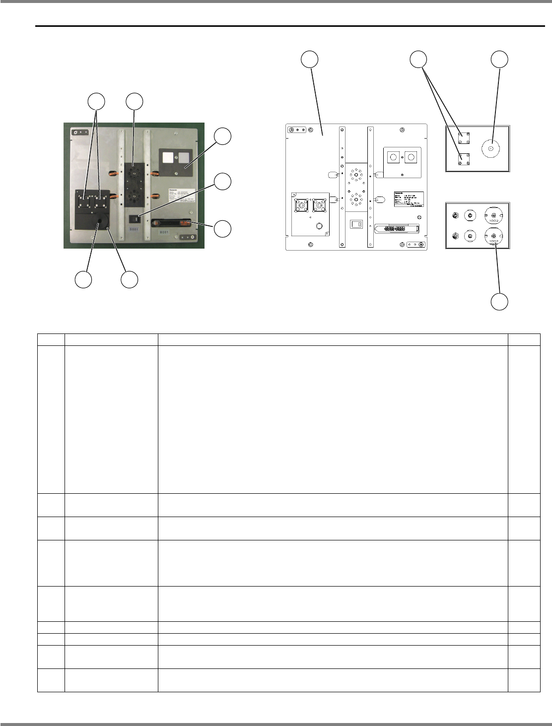
No. Unit name Function Qty
1 Jig station
Used for calibration of the head parameters after head replacement.
Common among 12-nozzle head, 8-nozzle head and 2-nozzle head.
Power rating: 12 VDC (AA battery
×
8)
Please obtain them by yourself.
For information on how to replace the batteries, see “11.3.1 Battery
Replacement of NPM” - “3 Replacing the Battery for the Jig Station.”
CAUTION
If the batteries are left in, they may leak; therefore, when you will not
use the jig station for a long period, they should be removed and
stored.
Mass: 1.5
kg
, overall dimensions: 240 mm (W)
×
215 mm (D)
×
35 mm (H)
1
2 Jig components
Used for calibration at the jig station (1).
Place them on the jig station when in use.
2
3
Line camera LED
light luminosity jig
Used for calibration of the line camera LED light luminosity at the jig station
(1). Place them on the jig station when in use.
1
4
Nozzles for
calibration
Used for calibration at the jig station (1).
For 12-nozle head: 153S nozzle
For 8-nozzle head: 184 nozzle
For 2-nozle head: 1003 nozzle
2
each
5
Head camera LED
light luminosity jig
storage stage
The jig to be used for calibration of the head camera LED light luminosity is
set here.
---
6 Main power switch The green LED is lit up when power is turned ON. ---
7 Photo sensor Detects the jig components (2). ---
8
Jig recognition
stage
The jig components (2) are mounted and recognized here during calibration.
---
9 Jig storage stage
The jig components (2) and the LED light luminosity jigs are set here before
calibration.
---
6
5
7
9
8
1 2 3
4
3
2
NPM
Maintenance Edition
9.9 Jig Station
Page 9-58 EJM9BE-MB-09M-21
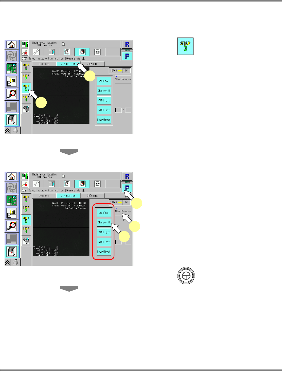
This procedure is common to 12-nozzle, 8-nozzle, and 2-nozzle heads.
∗
Make sure there is no nozzle in the nozzle changer.
∗
Remove all support-pins before performing calibration.
1
Press .
2
Press [Jig station].
∗
Check that no PCBs remain in the machine.
3
Select a table.
∗
Select the target table for calibration.
4
Select all the measurement items.
•
The selected items are displayed in light blue.
(The deselected items are grayed out.)
5
Press + [StartMeasure].
UnitCalibJigStation-01E02
4
3
5
UnitCalibJigStation-01E02
1
2