NPM Calibration Manual-En.pdf - 第60页
NPM Maint en anc e E di ti on 9.9 Ji g Stati on EJM9BE-M B-09M-21 Page 9-59 6 Press + [Run]. • T he conv e yor widt h is adjusted t o 215 mm. 7 Press + [OK]. • T he head mov es to the r etracti on positi on. 8 Turn OFF t…
NPM
Maintenance Edition
9.9 Jig Station
Page 9-58 EJM9BE-MB-09M-21
This procedure is common to 12-nozzle, 8-nozzle, and 2-nozzle heads.
∗
Make sure there is no nozzle in the nozzle changer.
∗
Remove all support-pins before performing calibration.
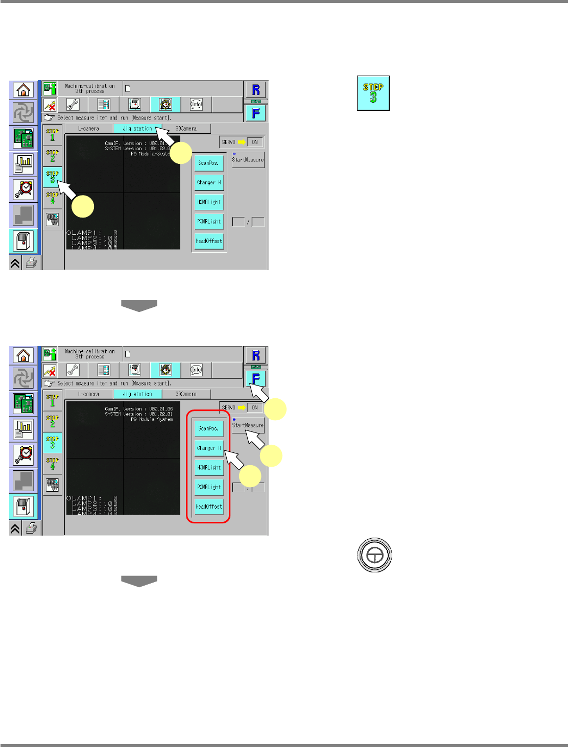
1
Press .
2
Press [Jig station].
∗
Check that no PCBs remain in the machine.
3
Select a table.
∗
Select the target table for calibration.
4
Select all the measurement items.
•
The selected items are displayed in light blue.
(The deselected items are grayed out.)
5
Press + [StartMeasure].
UnitCalibJigStation-01E02
4
3
5
UnitCalibJigStation-01E02
1
2
NPM
Maintenance Edition
9.9 Jig Station
EJM9BE-MB-09M-21 Page 9-59
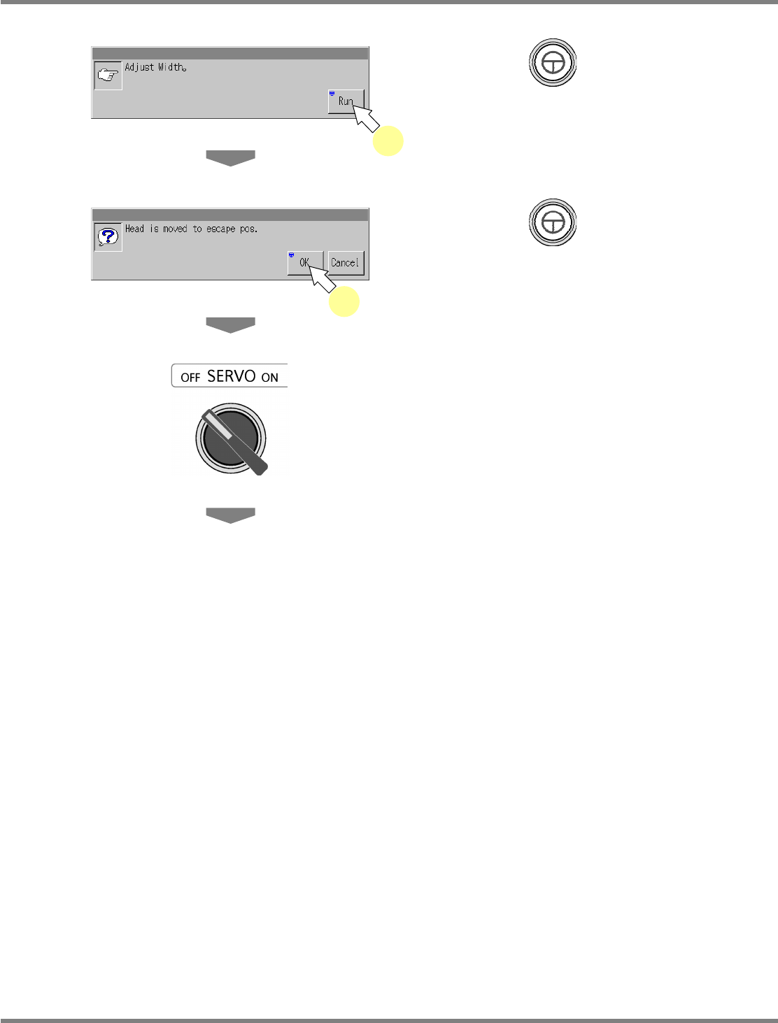
6
Press + [Run].
•
The conveyor width is adjusted to 215 mm.
7
Press + [OK].
•
The head moves to the retraction position.
8
Turn OFF the servo switch.
9
Open the safety cover.
6
7
NPM
Maintenance Edition
9.9 Jig Station
Page 9-60 EJM9BE-MB-09M-21
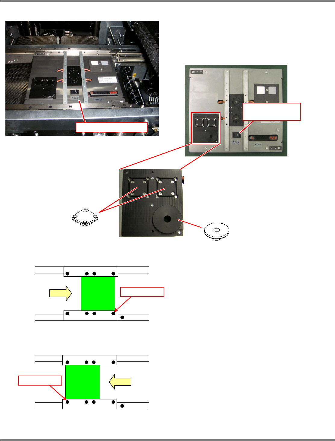
10
Set the jig station.
∗
Set the jig components and the light
luminosity jig onto the jig station beforehand.
Jig station
∗
Set the jig station with its end fit to the
reference mark on the upper surface of the
front rail.
11
Turn ON the power supply switch of
the jig station.
∗
Check that the LED lamp on the power supply
switch is lit.
Jig station
Reference mark
In left right flow
Reference mark
In right left flow
Jig component
Light luminosity jig
Power supply switch
(LED lamp)
∗
As shown in the left photo, place the jig
component and light luminosity jig to the
jig station.
These jigs have no particular orientation.