NPM Calibration Manual-En.pdf - 第69页
NPM Maint en anc e E di ti on 9.10 3D Camer a Page 9-68 EJM9BE-M B-09M-21 12 Close the safe ty cover. 13 Turn ON the se rvo switch. 14 Press + [OK]. • T he head mov es to the worki ng posi tion. 15 Set the nozz le. • W h…
NPM
Maintenance Edition
9.10 3D Camera
EJM9BE-MB-09M-21 Page 9-67
10
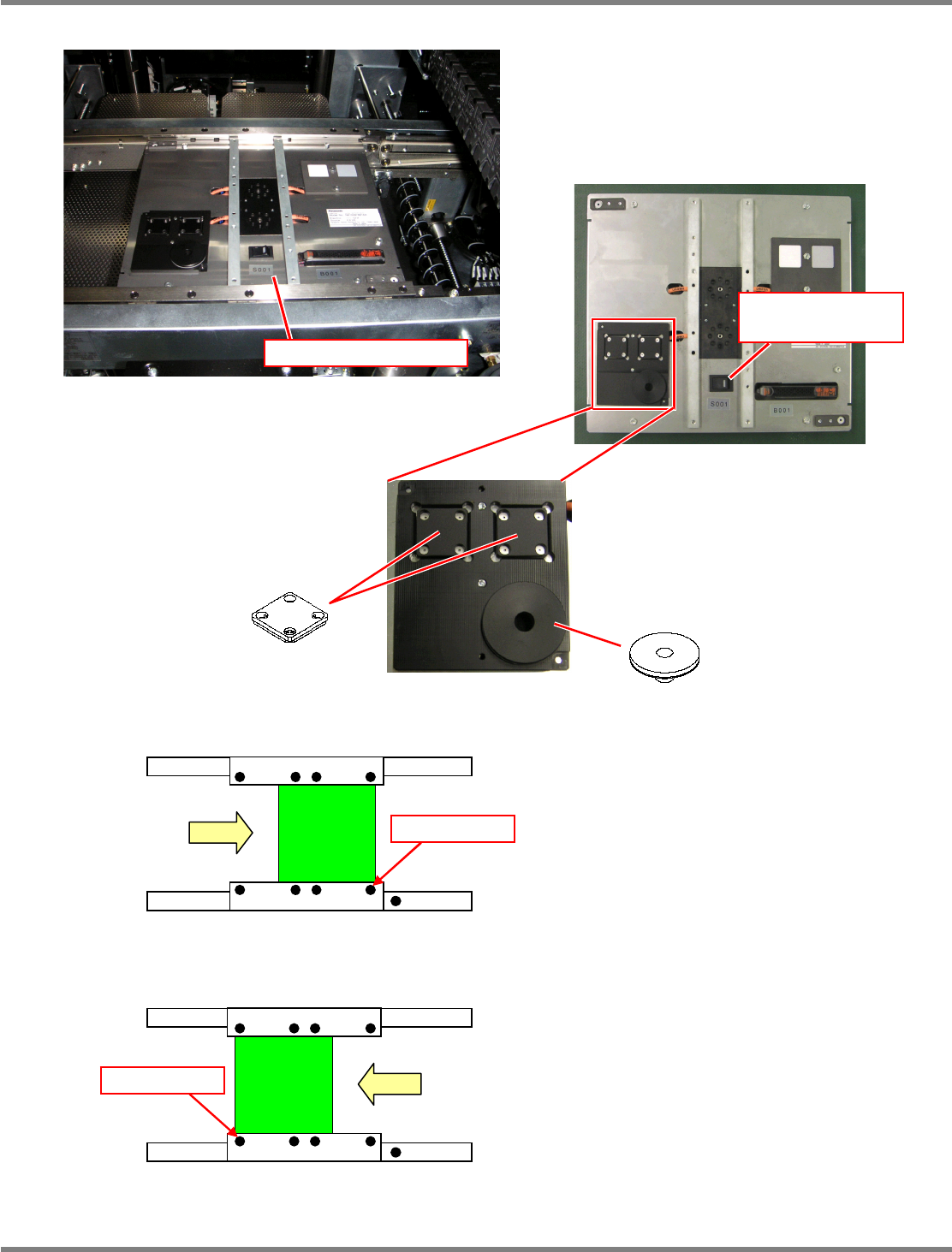
Set the jig station.
∗
Set the jig components and the light
luminosity jig onto the jig station beforehand.
Jig station
∗
Set the jig station with its end fit to the
reference mark on the upper surface of the
front rail.
11
Turn ON the power supply switch of
the jig station.
∗
Check that the LED lamp on the power supply
switch is lit.
Jig station
Reference mark
In left right flow
Reference mark
In right left flow
Jig component
Light luminosity jig
Power supply switch
(LED lamp)
∗
As shown in the left photo, place the jig
component and light luminosity jig to the
jig station.
These jigs have no particular orientation.
NPM
Maintenance Edition
9.10 3D Camera
Page 9-68 EJM9BE-MB-09M-21
12
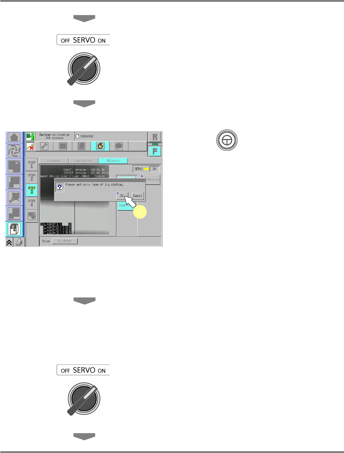
Close the safety cover.
13
Turn ON the servo switch.
14
Press + [OK].
•
The head moves to the working position.
15
Set the nozzle.
•
When the head has returned to the working
position, set the nozzle.
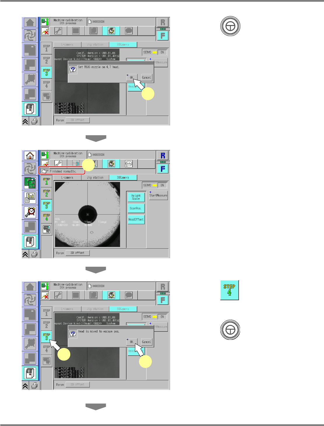
16
Attach the nozzle.
8-nozzle head
∗
Attach the No.184 nozzle to the nozzle
positions 3 and 6.
2-nozzle head
∗
Attach the No.1003 nozzles to all the nozzle
positions.
17
Close the safety cover.
18
Turn ON the servo switch.
UnitCalibCamera3D-03E00
14
NPM
Maintenance Edition
9.10 3D Camera
EJM9BE-MB-09M-21 Page 9-69
19
Press + [OK].
•
The calibration is carried out.
20
Check that it is successfully complete.
∗
Perform steps 3–22 for also the other table.
∗
In this calibration, when it is complete
successfully, the measured parameters will be
saved.
21
Press .
22
Press + [OK].
•
The head moves to the retraction position.
UnitCalibCamera3D-04E00
19
UnitCalibCamera3D-02E00
21
22
UnitCalibCamera3D-05E00
20