NPM Calibration Manual-En.pdf - 第87页
NPM Maint en anc e E di ti on 9.13 T ray Page 9-86 EJM9BE-M B-09M-21 17 Turn OFF the se rvo switch. 18 Open the s afety cover. 19 Detach the nozzles. 20 Close the safe ty cover. 21 Turn ON the se rvo switch. 22 Press + […
NPM
Maintenance Edition
9.13 Tray
EJM9BE-MB-09M-21 Page 9-85
14
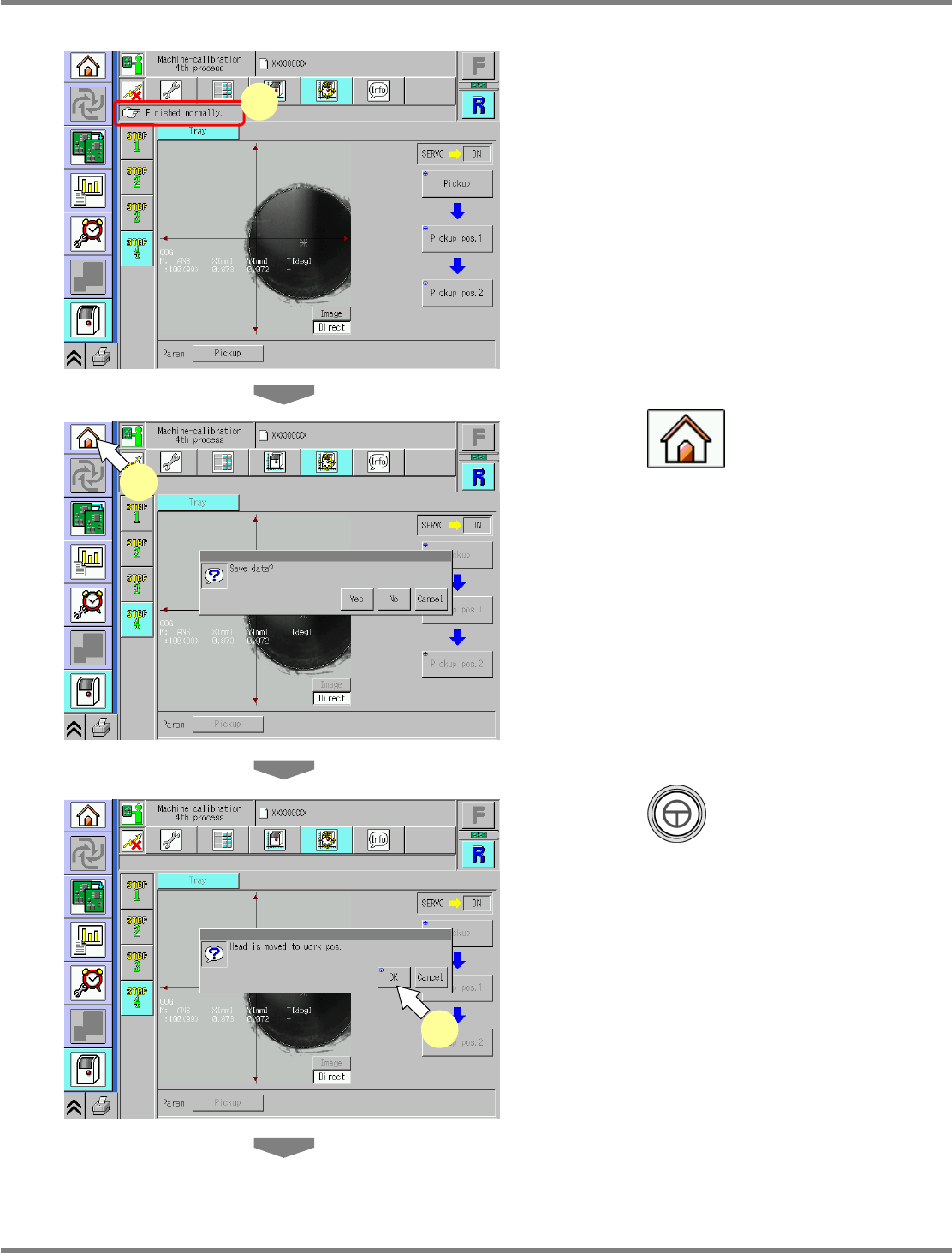
Check that it is successfully complete.
15
Press .
•
When exiting this screen to the other one, you
are always prompted to save the data.
∗
To save the data obtained by the calibration,
press [Yes].
•
If you press [No], the return-to-origin process
is carried out and the data obtained by the
calibration are lost.
•
After the above operation, the next screen is
displayed.
16
Press + [OK].
•
The head moves to the retraction position.
UnitCalibTrayPos-06E00
15
UnitCalibTrayPos-05E00
14
UnitCalibTrayPos-07E00
16
NPM
Maintenance Edition
9.13 Tray
Page 9-86 EJM9BE-MB-09M-21
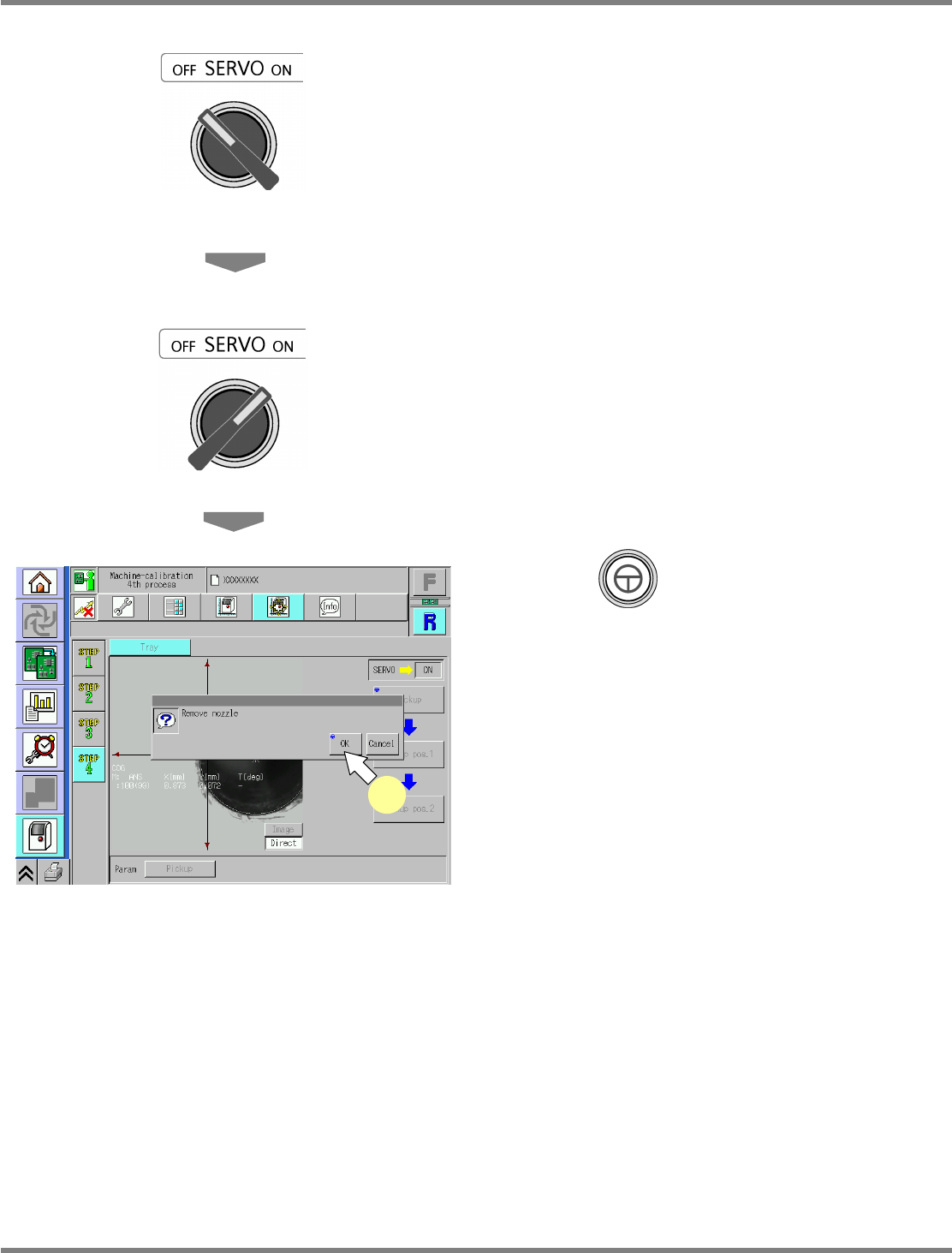
17
Turn OFF the servo switch.
18
Open the safety cover.
19
Detach the nozzles.
20
Close the safety cover.
21
Turn ON the servo switch.
22
Press + [OK].
•
After the head moves to the origin position,
the screen selected in step 16 is displayed.
UnitCalibTrayPos-08E00
22

NPM
Maintenance Edition
9.14 Accuracy Verification
EJM9BE-MB-09M-21 Page 9-87
9.14 Accuracy Verification
This section describes the procedures for measuring the machine’s placement accuracy and registering
the each-placement-position-angle offset by using that measured result.
9.14.1 Overview
1 Brief Description of Processes
The dedicated MCDATA (production program) is used for accuracy verification and registering
the each-placement-position-angle offset.
This work can be performed only by using the dedicated MCDATA.
When the each-angle offset is reflected, machine parameters in the machine will be rewritten.
You are recommended to save the current data beforehand just in case.
The following flow shows a brief description of processes.
1. Preparation for Production
Selection of MCDATA (Production Program)
Preparation for Placement, Checking of Pickup Positions, Setting of Nozzles
2. Checking and Reflection of Placement
Placement
Checking and Reflection of Placement Results
3. Checking of Placement Accuracy
Placement
Checking of Placement Results
2 Head Types, Work Details, and Components
The work to do varies according to the installed head pattern.
The each-angle offset will be reflected on Chip, Micro, General-purpose, and 3D (OP).
Chip: Reflected on 12 N and 8 N placement accuracy
Micro: Offset dedicated to 0402 components
General-purpose: Reflected on 2 N placement accuracy and general-purpose 8 N-ready
components (
12 or larger)
3D (OP): Reflected when the optional 3D sensor is used
Shown below are the nozzles to be used for each head.
Head Chip Micro General-purpose 3D
12-nozzle head 230CS x 12 230ZS x 12 --- ---
8-nozzle head 230C x 8 230Z x 8 184 x 2 184 x 2
2-nozzle head --- --- 1003 x 2 1005 x 2