NPM Calibration Manual-En.pdf - 第92页
NPM Maint en anc e E di ti on 9.14 Accu racy Ve rificat ion EJM9BE-M B-09M-21 Page 9-91 ② Prep ara tio n fo r Pl ac em ent, C hecking of P ick up P ositi ons, S etti ng of Nozzles 1 Set the nozz les to the nozzle ho l de…
NPM
Maintenance Edition
9.14 Accuracy Verification
Page 9-90 EJM9BE-MB-09M-21
9.14.2 Detailed Processes
This subsection details the processes using the operation screens.
1 Preparation for Production
①
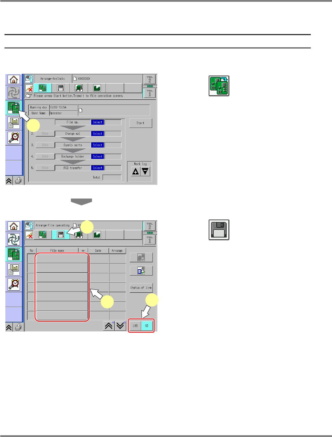
Selection of MCDATA (Production Program)
1
Press .
Select the changeover screen.
2
Press .
3
Select the source to load.
Select the source to load.
Data is input from the SD card.
4
Select the MCDATA (production
program) copied to an SD card from
the CD-ROM.
∗
This step is the same as that for usual
preparation for production.
ChangeWorkState-01E04
1
ChangeFileOpeProData-01E01
2
3
4
NPM
Maintenance Edition
9.14 Accuracy Verification
EJM9BE-MB-09M-21 Page 9-91
②
Preparation for Placement, Checking of Pickup Positions, Setting of
Nozzles
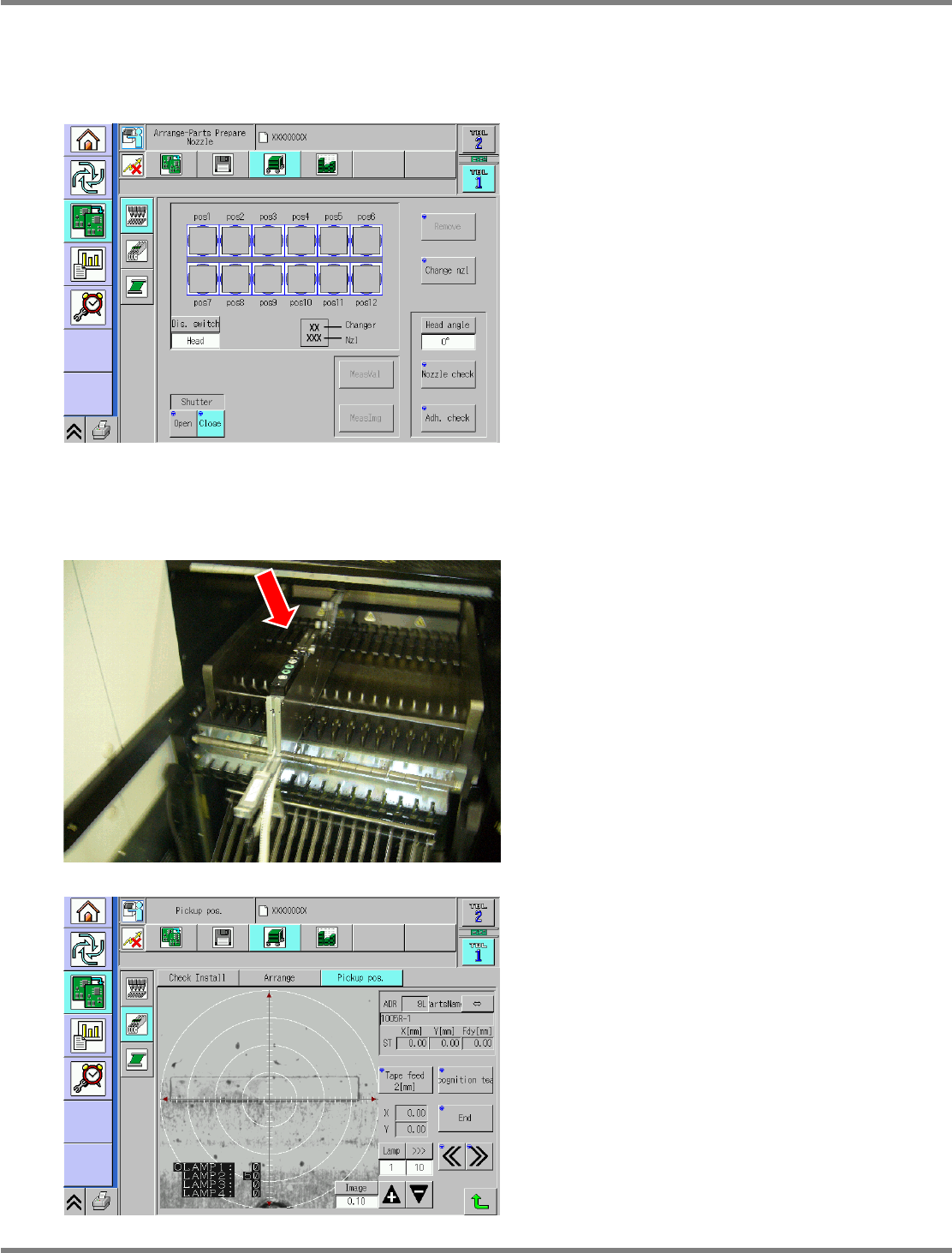
1
Set the nozzles to the nozzle holders.
Set the appropriate nozzles to the nozzle
holders.
∗
This step is the same as that for usual
preparation for production.
2
Supply parts.
Supplying parts (for chips)
•
Set the jig chips to the feeder and install it to
the No. 7 slot.
For placing in front and rear beams, set on the
front and the rear.
∗
This step is the same as that for usual
preparation for production.
•
For chip placement, the pockets in the feeder
are taught as appropriate.
∗
This step is the same as that for usual
preparation for production.
ChangeNozzleSet-01E03
ChangeFeederPickupTeach-01E01
NPM
Maintenance Edition
9.14 Accuracy Verification
Page 9-92 EJM9BE-MB-09M-21
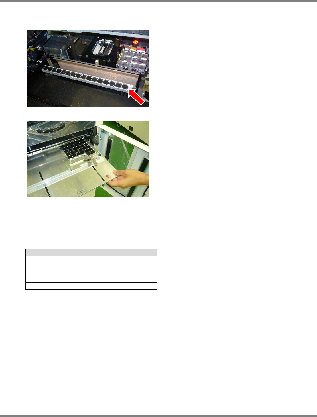
Supplying parts (for general-purpose and 3D (OP))
•
For setting to the feeder cart, obtain JIG_BGA
(N610087876AA) from the tray, and set them
to the supply table (N610074266AA).
The supply table has a 2-stage configuration,
where 16 pieces of JIG_BGA
×
2 stages can be
set.
∗
JIG_BGA should be placed in alignment.
•
Set the tray to the slot 1.
This step is the same as that for usual
preparation for production.
Install it to the tray pallet together with the
aluminum case.
∗
Pay attention to the installation direction.
The individual JIG_BGA does not carry a sense
of direction.
3
Obtain a glass PCB.
•
A glass PCB, a background plate and mirrors
are included in the glass board set
(N610088868AA) for checking placement
accuracy.
∗
The usage of the included materials varies
with the parts whose accuracy is to be
verified.
To mount and verify JG_BGA, use the black
background as it is.
To mount and verify the chip component (Jig
chip: ERJJ02AAAAAV, 0402R, etc.), insert a
mirror between the glass and background
plate.
Part Background
JIG_BGA Black sponge
(Set the background plate as it
is.)
Jig chip Mirror
0402R Mirror
Parts and background conditions