1OM-1505-004_w.pdf - 第123页
1OM-1505 3-18 3. PCB Replenishment : Chap.3 3. PCB Replenishment When the machine gets short of PCBs during automatic operation, the input machine produces an error alarm or the machine stops automatically. (1) When the …
1OM-1505
2. Squeegee Replacement and Solder Paste Replenishment : Chap.3
3-17
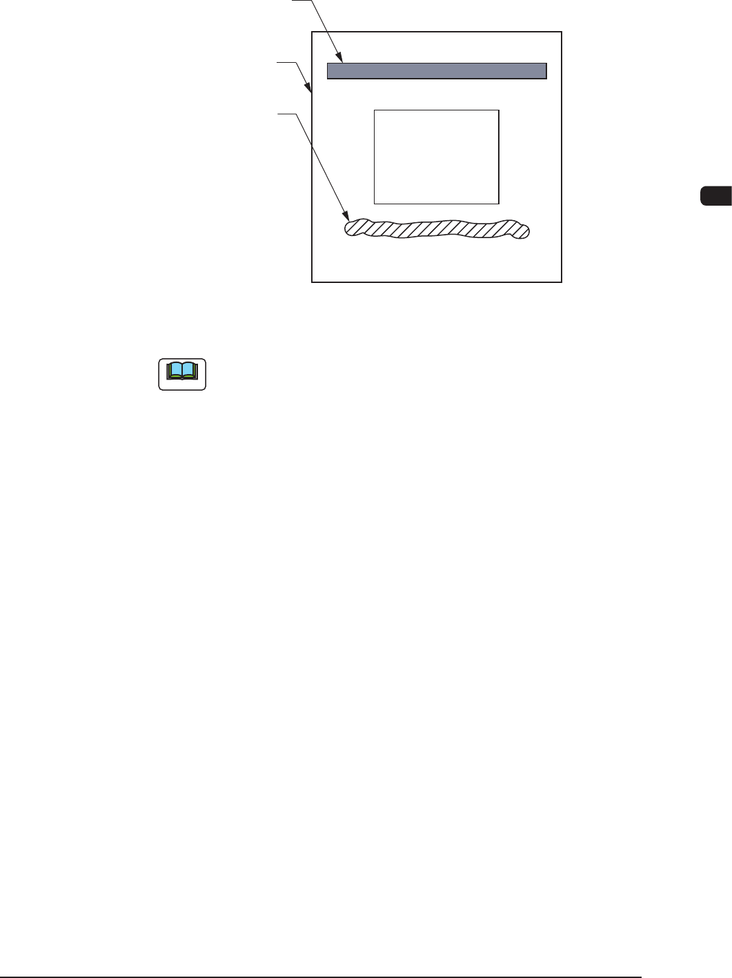
(5) Open the transparent covers on the machine front and replenish the solder
paste over the left solder paste on the stencil.
Squeegee
Printing Pattern
Stencil
Solder Paste
(Rear Side of Machine)
(Front Side of Machine)
F1C18
Note
Depending on the condition of the machine stop, the solder paste is located
on the rear side of the stencil.
(6) Close the transparent covers.
(7) Press the cover lock switch.
(8) Press the [STOP] button on the operation panel.
(The Automatic Operation is re-started.)
1002-002

1OM-1505
3-18
3. PCB Replenishment : Chap.3
3. PCB Replenishment
When the machine gets short of PCBs during automatic operation, the input
machine produces an error alarm or the machine stops automatically.
(1) When the input machine has issued an error alarm, follow the step
below.
Replenish the input machine with PCBs and re-start the automatic operation.
(2) When the machine has stopped automatically, follow the step below
The input machine has stopped automatically in a normal condition.
In normal cases, it means that the production is completed.
0906-001
1OM-1505
3. PCB Replenishment : Chap.3
3-19
3.1 Preparation for PCB's
In the case of normal automatic operation, conrm that PCB's are prepared in the
input machine.
When this machine is operated singly (a printing test, etc.), follow the
steps below.
•
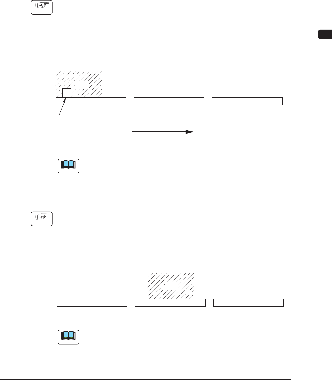
PCB Size of 330 mm or less
Procedure
(1) Press the cover lock switch and open the transparent covers.
(2) Set a PCB on the L conveyor (input conveyor) such that the PCB detection
sensor is turned on (the red LED of the sensor illuminates).
PCB
L Conveyer
(Input Conveyor) (PCB Positioning Section)
R Conveyer
(Output Conveyor)
L Conveyor PCB Detection L Sensor
PCB Flow Direction
F1C19
Note
The gure shows that the PCB flows from left to right, based on "Front
Reference".
•
PCB Size of more than 330 mm
Procedure
(1) Press the cover lock switch and open the transparent covers.
(2) Set the PCB on the PCB positioning section as shown in the following gure.
PCB
L Conveyer
(Input Conveyor) (PCB Positioning Section)
R Conveyer
(Output Conveyor)
F1C20
Note
The PCB flow direction ("Left to Right" and "Right to Left") is common to both
cases.
0906-001