1OM-1505-004_w.pdf - 第140页
1OM-1505 3. Program Change Operation: Chap.4 4-1 1 3.8 Stencil Attachment This section describes the attachment procedure of the stencil prepared for the product model. Stencil Size Change For the stencil size, the follo…
1OM-1505
4-10
3. Program Change Operation: Chap.4
(6) While pushing the squeegee tightly against the lower surface of the squeegee
holder, push down the mechanical valve switch to the right side to clamp the
squeegee.
Note
(a) The squeegee should be clamped from the rear side of the holder and
then from the front side.
(b) When the squeegee is pulled downward using the reverse procedure
of the above, it can be removed.
NOTICE
Hold the squeegee securely and attach it.
If the squeegee falls down on the stencil, the stencil might
be damaged.
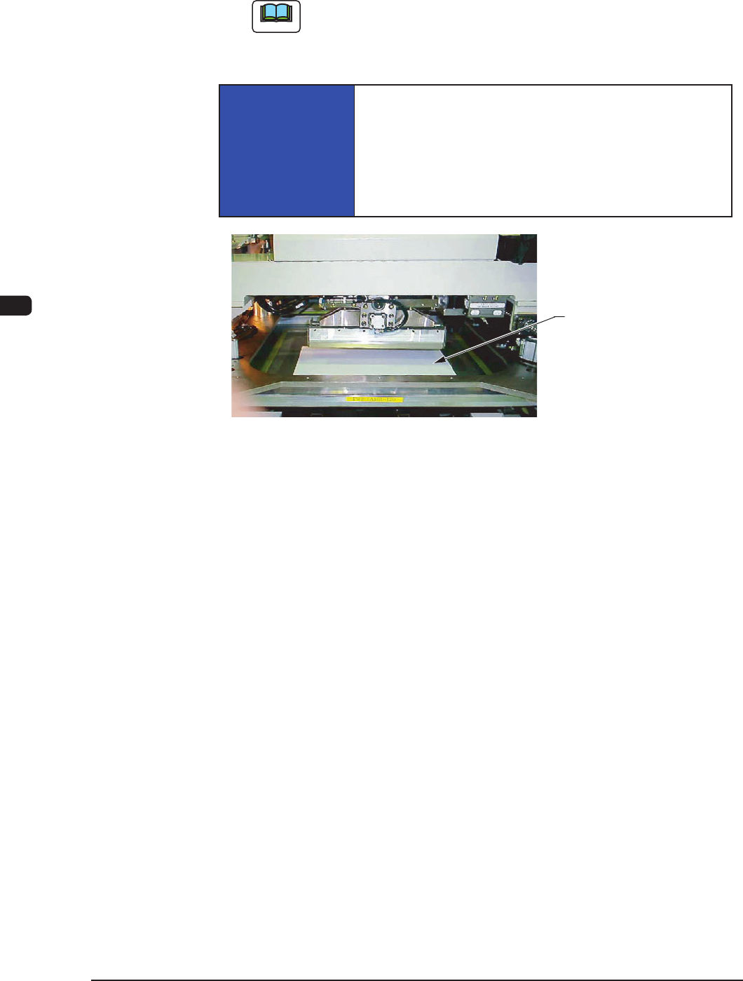
It is recommended that a protective plate should be
prepared by the user and placed it on the stencil.
Stencil Protective Plate
Stencil Protective Plate Use Example F1D7
1002-002
1OM-1505
3. Program Change Operation: Chap.4
4-11
3.8 Stencil Attachment
This section describes the attachment procedure of the stencil prepared for the
product model.
Stencil Size Change
For the stencil size, the following 7 types are provided.
750 × 750, 7
36 × 736, 720 × 720, 750 × 650, 650 × 750,
650 × 550, 600 × 550 (Option)
Note
Stencil Size of "600
×
550" is an option.
The stencil with the above size can be attached using the optional
attachment.
Procedure
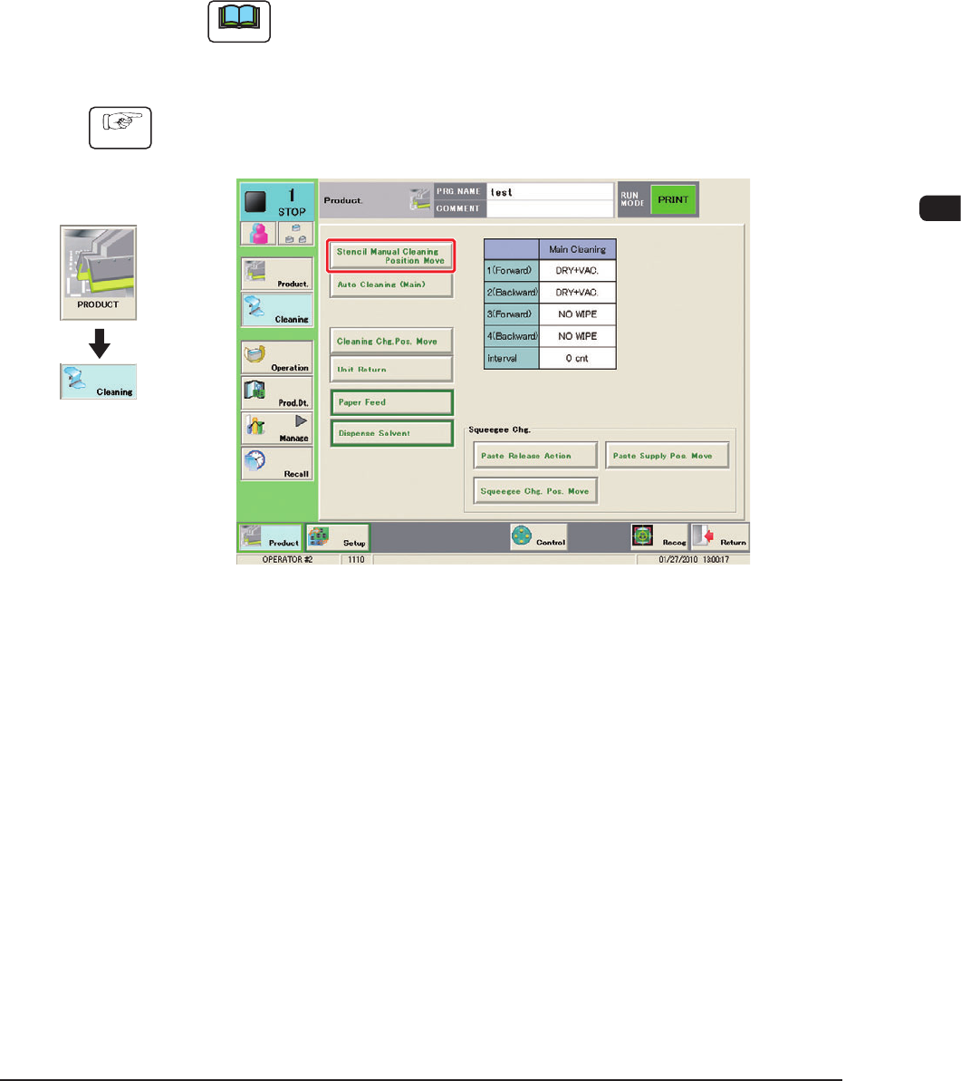
(1) Press the [Stencil Manual Cleaning Position Move] button in the
"CLEANING" window.
F1D8
(2) Press the [START] button on the operation panel.
(The stencil will be moved to the front.)
(3) Press the cover lock switch.
(4) Open the transparent cover on the machine front.
1002-002
Graphic
Development
1OM-1505
4-12
3. Program Change Operation: Chap.4
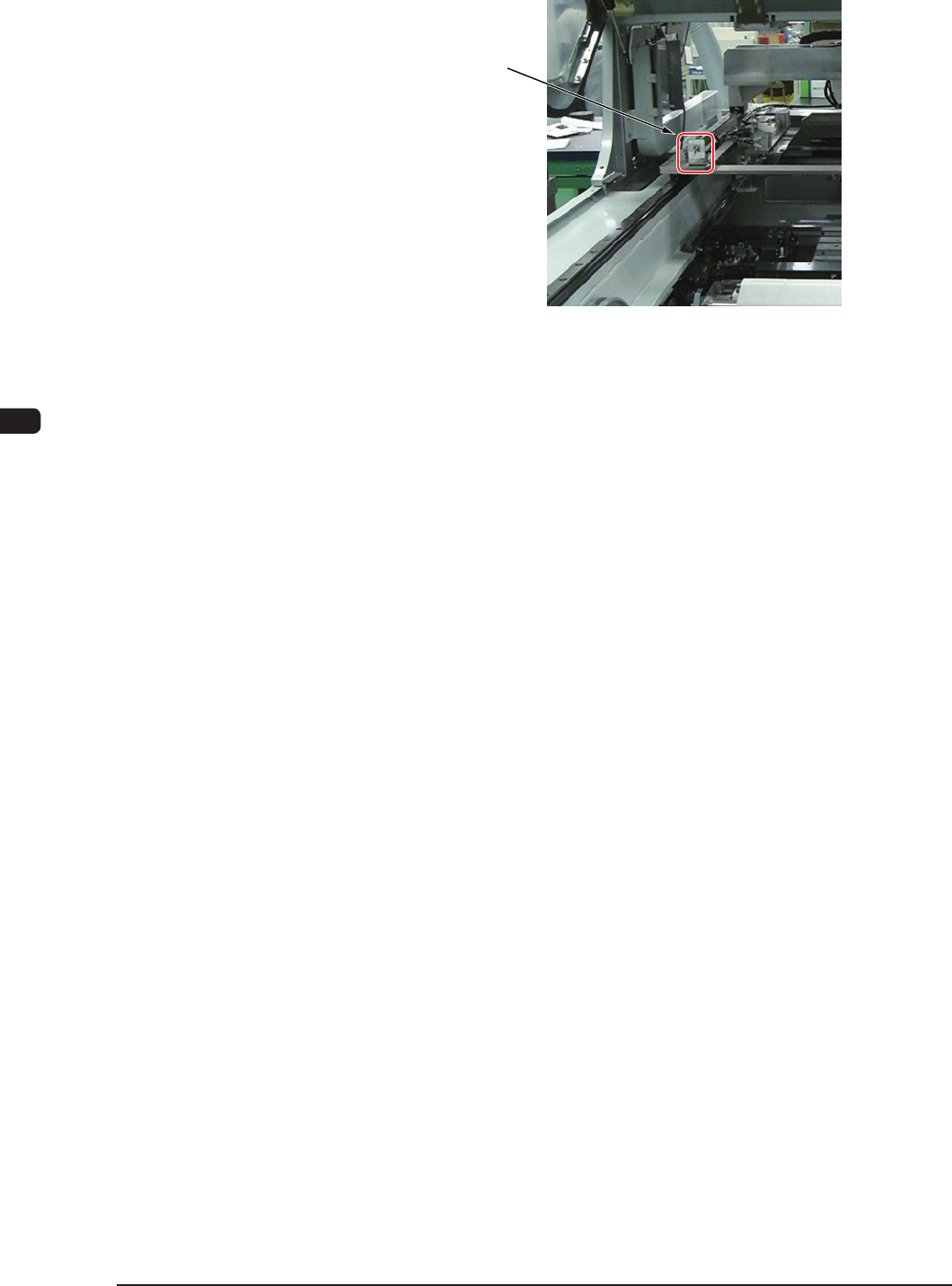
(5) Press down the mechanical valve switch to the rear to release the stencil
clamping cylinder.
Stencil Clamping
Mechanical Valve
Switch
F1D9
(6) Draw the stencil to the front to remove.
(7) Adjust the stencil direction.
0906-001