1OM-1505-004_w.pdf - 第144页
1OM-1505 3. Program Change Operation: Chap.4 4-15 1002-002 (14) Close the transparent covers and press the cover lock switch. (15) Press the [Stencil Manual Cleaning Position Move] button in the "CLEANING" wind…
1OM-1505
4-14
3. Program Change Operation: Chap.4
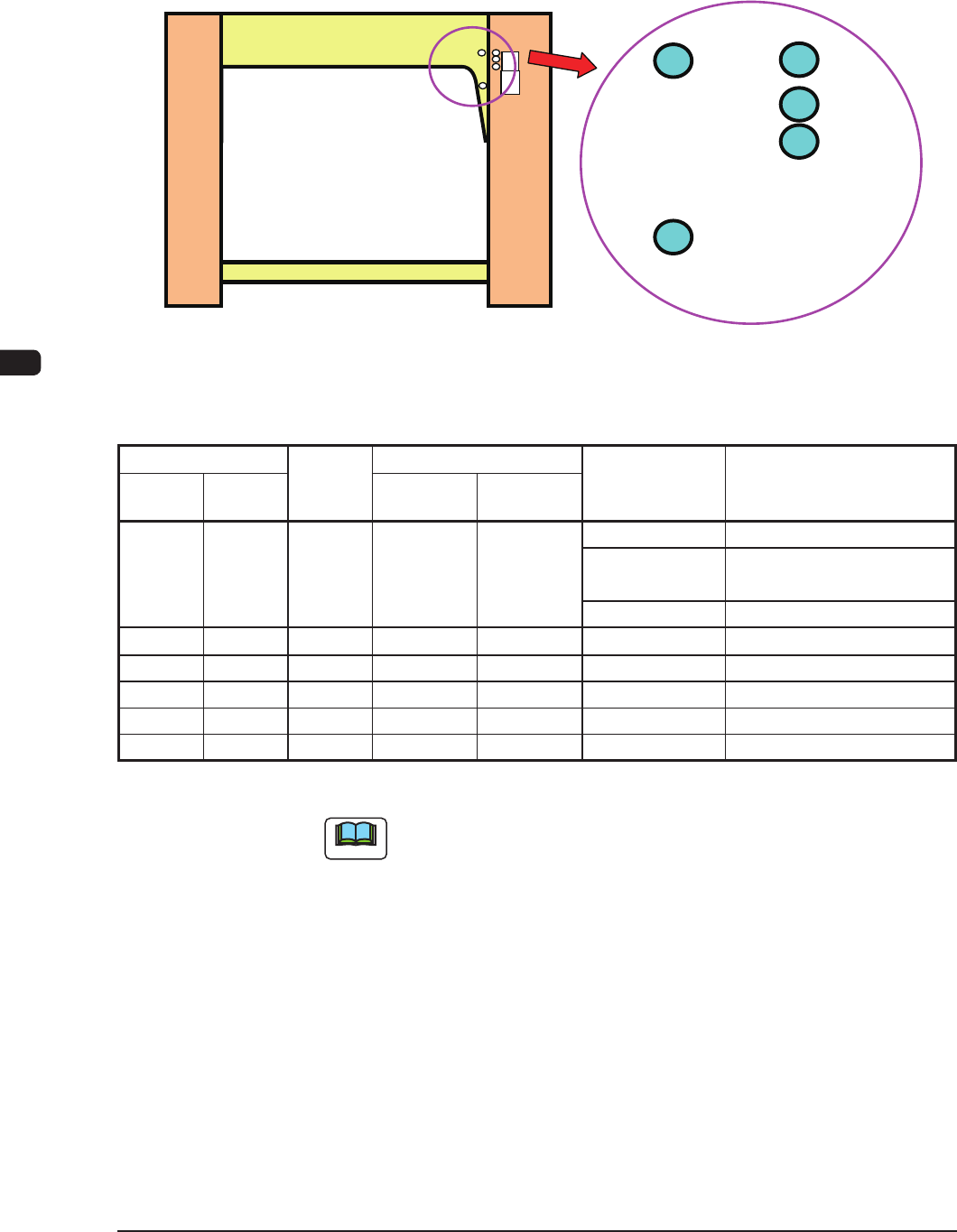
(13) Change the stencil attachment position by means of changing the positions of
the stopper pins as shown in the table "T1D1" according to the stencil size in
the direction Y from the machine rear side, printing reference, PCB transfer
reference and PCB size in direction X.
A
B
C
D
E
F1D12
Stopper Pin Positions and Printable PCB Width Size Range (mm)
Stencil Size
Pin
Position
Max. Printable PCB Size
Printing
Reference
Paste Releasing
Action Constraints
X
direction
Y
direction
X direction Y direction
750 750 A 510 460 Rear Unavailable
Center Unavailable for 430 mm or
more in PCB Direction Y
Front Unavailable for 445 mm
736 736 B 490 381
Rear/Center/Front
None
720 720 C 470 381
Rear/Center/Front
None
750 650 E 510 381
Rear/Center/Front
None
650 750 D 330 381
Rear/Center/Front
None
650 550 E 330 250
Rear/Center/Front
None
Unit : mm
T1D1
Note
In the case of the printing under the condition except for that in T1D1,
contact the Sales Dept. in
Hitachi High-Technologies
or our sales agent.
1002-002
1OM-1505
3. Program Change Operation: Chap.4
4-151002-002
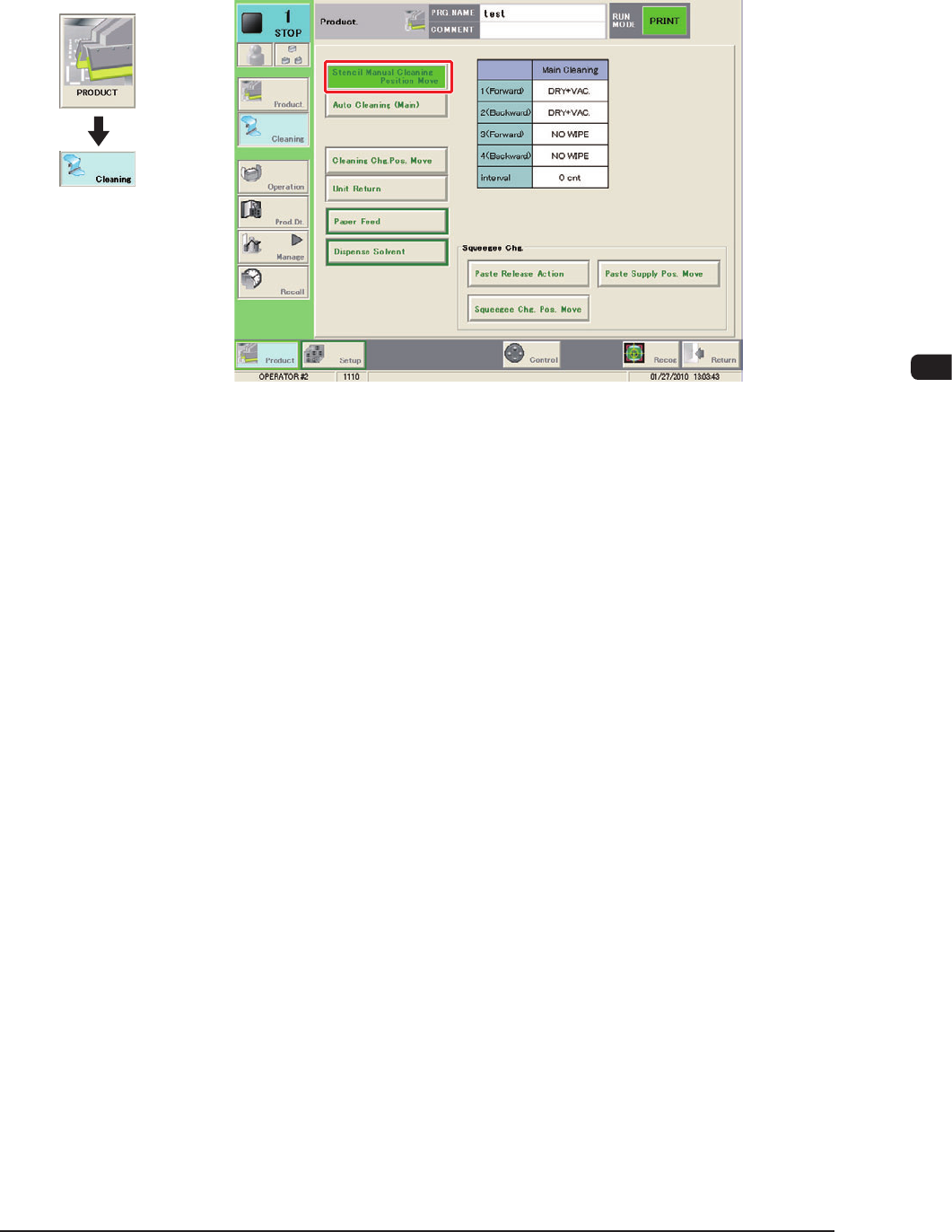
(14) Close the transparent covers and press the cover lock switch.
(15) Press the [Stencil Manual Cleaning Position Move] button in the
"CLEANING" window.
F1D12-1
(16) Press the [START] button on the operation panel.
(The stencil will be moved to the front.)
Graphic
Development
1OM-1505
4-16
3. Program Change Operation: Chap.4
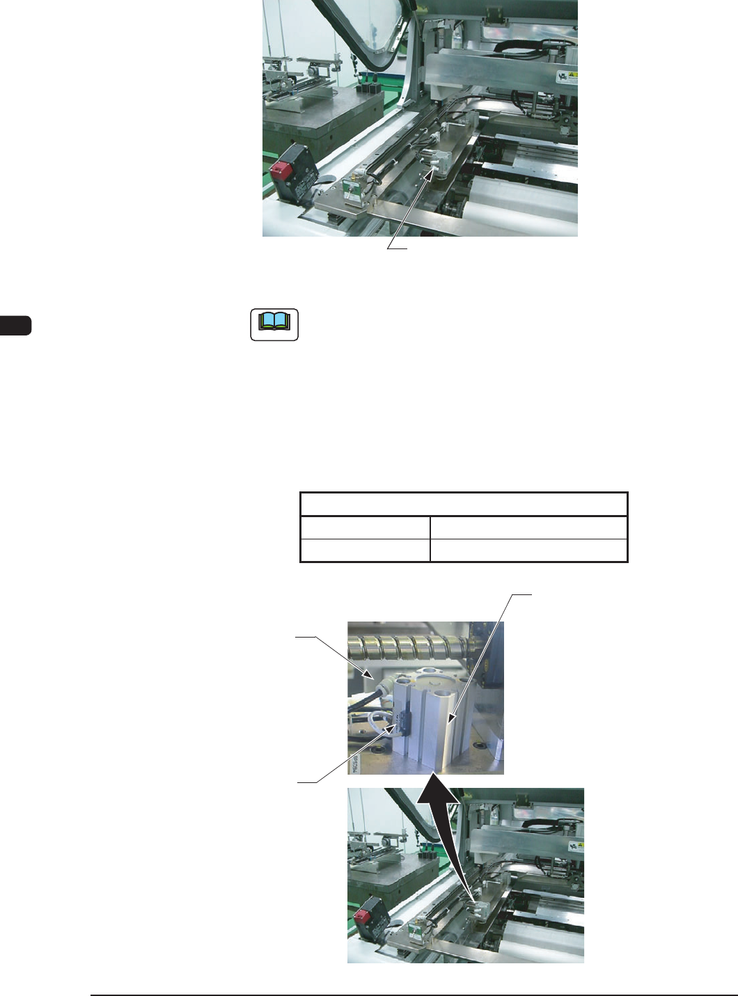
(17) Set the stencil onto the stencil holder and push down the stencil clamping
mechanical valve switch to the front to clamp the stencil.
Stencil Clamping Mechanical Valve Switch
F1D13
Note
When the machine is delivered, the stencil clamping cylinder lead
switch position has been setup on the assumption of the stencil
thickness of 30 to 40 mm or less.
In the case that the stencil thickness is more than 40 mm, adjust the
lead switch position using the following procedure.
Fasten the lead switch set screw using the precision screwdriver
and adjust the lead switch so that the lead switch LED is located as
follows.
Stencil Size
Clamped Unclamped
OFF ON
T1D2
Stencil Clamping Cylinder
Lead Switch
Set Screw
Lead Switch
F1D14
1002-002