1OM-1505-004_w.pdf - 第145页
1OM-1505 4-16 3. Program Change Operation: Chap.4 (17) Set the stencil onto the stencil holder and push down the stencil clamping mechanical valve switch to the front to clamp the stencil. Stencil Clamping Mechanical Val…
1OM-1505
3. Program Change Operation: Chap.4
4-151002-002
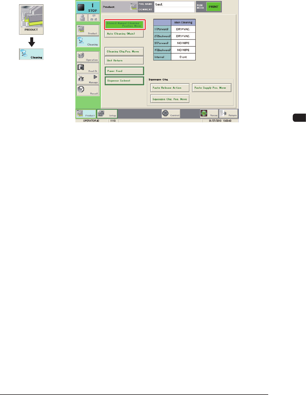
(14) Close the transparent covers and press the cover lock switch.
(15) Press the [Stencil Manual Cleaning Position Move] button in the
"CLEANING" window.
F1D12-1
(16) Press the [START] button on the operation panel.
(The stencil will be moved to the front.)
Graphic
Development
1OM-1505
4-16
3. Program Change Operation: Chap.4
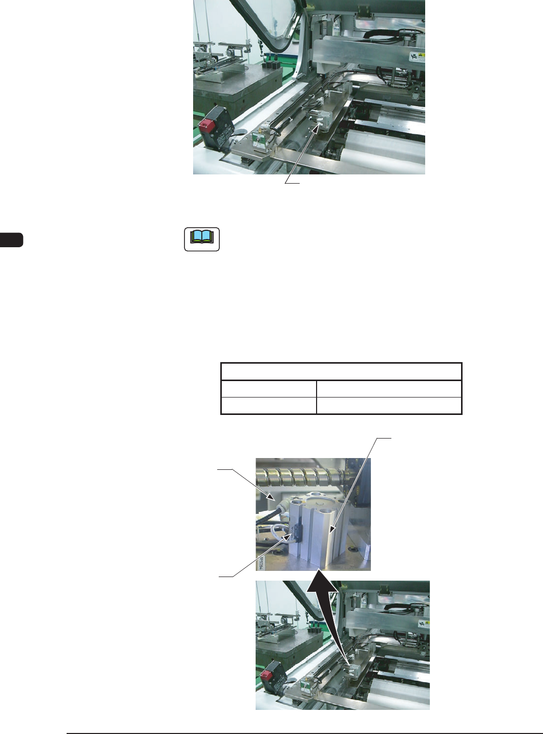
(17) Set the stencil onto the stencil holder and push down the stencil clamping
mechanical valve switch to the front to clamp the stencil.
Stencil Clamping Mechanical Valve Switch
F1D13
Note
When the machine is delivered, the stencil clamping cylinder lead
switch position has been setup on the assumption of the stencil
thickness of 30 to 40 mm or less.
In the case that the stencil thickness is more than 40 mm, adjust the
lead switch position using the following procedure.
Fasten the lead switch set screw using the precision screwdriver
and adjust the lead switch so that the lead switch LED is located as
follows.
Stencil Size
Clamped Unclamped
OFF ON
T1D2
Stencil Clamping Cylinder
Lead Switch
Set Screw
Lead Switch
F1D14
1002-002

1OM-1505
3. Program Change Operation: Chap.4
4-17
3.9 Stencil Recognition Test
Perform the stencil recognition test using the "Stencil Recog Test" tab sheet
(Operation Sequence: [MAINT] button in the main menu → [DEVICE CHECK]
button → [Stencil Recog Test] tab).
Reference
Refer to "8.2 Stencil Recognition Test" in "Chapter 2 (Vol. 3)" for details.
3.10 Stencil Recognition
Perform the stencil recognition after the stencil attachment or removal, power
input, system clearance or stencil coordinate change operation.
The stencil recognition operation is performed using the [Stencil Recog] button on
the "Semi-Auto Opn" tab sheet (Operation Sequence: ([PRODUCT CHG.] button
in the main menu → [INDIVIDUAL SET-UP] button → [Semi-Auto Opn] tab),
or the [Stencil Recog] button in the "CTRL" window.
Reference
Refer to "5.1 Semi-Auto Opn" in "Chapter 3 (Vol. 2)" or "2.4 Control Menu" in
"Chapter 2"for details.
3.11 Inaccurate Position Correction
When any positional deviation is found between the stencil opening and PCB
pattern, in the print check before the printing operation, correct the position
visually or using the PEC recognition camera.
This corrected data is reflected as parameters for "Printing Correction (Back)" and
"Printing Correction (For.)" in the "Print" tab sheet in the "Pattern Program" edit
window.
The positional deviation between the PCB and the stencil is checked or adjusted
using the "Inaccurate Posn. Correction" tab sheet in the "TEACHING" window
(Operation Sequence: [MAINT] button on the main menu → [TEACHING]
button → [Inaccurate Posn. Correction] tab).
Reference
Refer to "7.1 Inaccurate Position Correction" in "Chapter 3 (Vol. 2)" for details.
3.12 Solder Paste Replenishment
Put the solder paste on the stencil.
1002-002