1OM-1505-004_w.pdf - 第59页
1OM-1505 1-4 2. Names and Functions of Each Section : Chap.1 2.3 Cover Lock Switch Front Side of Machine Rear Side of Machine F1A4 The cover lock switch is used to allow the automatic operation and located in the front a…
1OM-1505
2. Names and Functions of Each Section : Chap.1
1-3
2.2 [EMERGENCY STOP] Switch
The [EMERGENCY STOP] switch can be used to stop the machine in an
emergency.
When one of the [EMERGENCY STOP] switch is pressed, the machine stops
immediately and the [POWER ON] button on the operation panel turns red.
[EMERGENCY STOP] Switch
F1A3
•
Locking the [EMERGENCY STOP] Switch
When one of the [EMERGENCY STOP] switch is pressed, the machine stops and
the switch is locked.
•
Unlocking the [EMERGENCY STOP] Switch
When one of the [EMERGENCY STOP] switch is pressed (locked), check and
remove the cause of the emergency stop. After that, recheck each section and turn
the switch clockwise to unlock.
Notice
The [EMERGENCY STOP] switches are used to intercept the controlled
power supply in an emergency.
Note
This machine is not provided with any emergency stop off function that can be
used to intercept the power supply to all loads in an emergency.
When "Emergency Switch Off" is required, it must be prepared outside the
machine on the customer side.
1002-003
1OM-1505
1-4
2. Names and Functions of Each Section : Chap.1
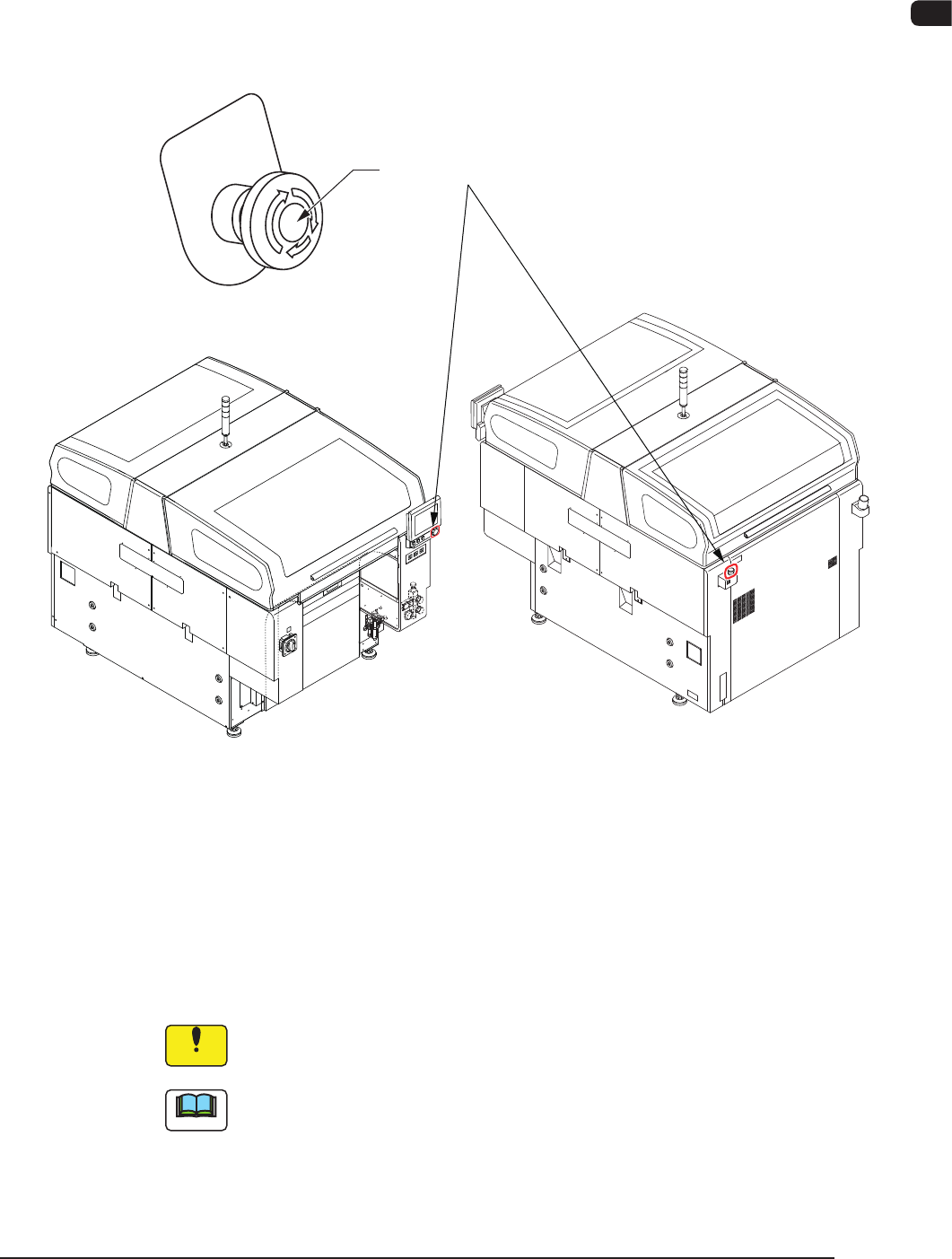
2.3 Cover Lock Switch
Front Side of Machine Rear Side of Machine
F1A4
The cover lock switch is used to allow the automatic operation and located in the
front and rear surfaces of the machine.
When this switch is in ON mode, the transparent covers can not be opened
because the electromagnetic locks are activated.
Also, while any of the transparent covers is opened, the LED of this switch can
not be turned ON.
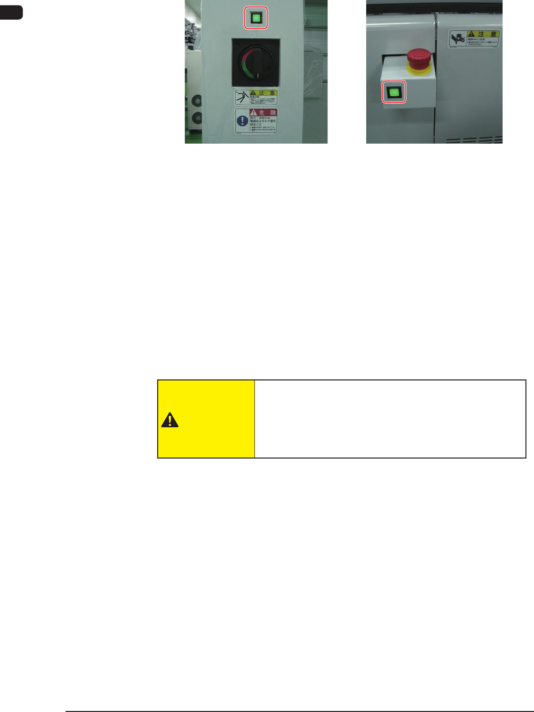
When this switch is pressed, the LED of the switch illuminates in green and the
transparent cover is in LOCK mode.
The automatic operation is performed with the transparent covers set in LOCK
mode.
When this switch is pressed again, the LED illuminates and the interlock is
cancelled.
CAUTION
When the cover lock switch is pressed, the interlock
function of the transparent covers is deactivated.
Do not operate the machine with the lock function
deactivated, except for the setup operation.
0906-001
1OM-1505
2. Names and Functions of Each Section : Chap.1
1-50906-001
Short Appendix: Cover Lock Switch
•
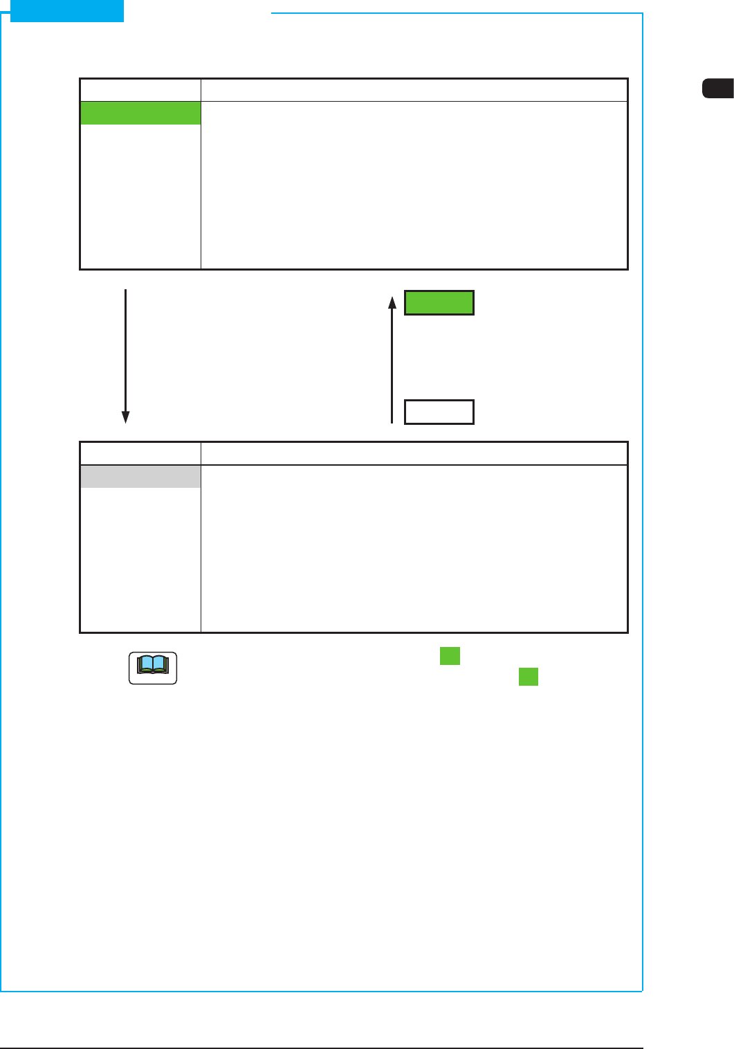
Cover Lock Switch
Switch Status Machine Status
LED ON Condition when the operator permits the "cover lock
operation"
•
Transparent Cover Electromagnetic Lock
: Locked
(Transparent Cover
Opening Operation
Unavailable)
LED ON
Switch ON Switch ON
(No Distinction between (No Distinction between
Short and Long Pushes) Short and Long Pushes)
LED OFF
Switch Status Machine Status
LED OFF
Condition when the operation does not permit the "cover
lock operation"
•
Transparent Cover Electromagnetic Lock
: Unlocked
(Transparent Cover
Opening/Closing
Operation Available)
Note
While the LED of the [Cover Lock] switch is "ON", power is supplied to the
main circuit of the beam with the [Cover Lock] switch kept "ON".