1OM-1505-004_w.pdf - 第64页
1OM-1505 2. Names and Functions of Each Section : Chap.1 1-9 2.6 Light T ower Red Y ellow Green Buzzer Light T ower F1A10 The light tower indicates the status of the machine with the lamps and buzzer sounds. • Lamp Color…
1OM-1505
1-8
2. Names and Functions of Each Section : Chap.1
2.5.2 Unlocking the Power Breaker
Remove the padlock from the lock lever of the power breaker.
Front Side of Machine
Lock Lever
Padlock
Power Breaker
F1A8
2.5.3 Locking the Power Breaker
Lock the power breaker with the padlock when the machine is not to be used for a
long period of time.
Power Breaker Locking Procedure with Padlock
Procedure
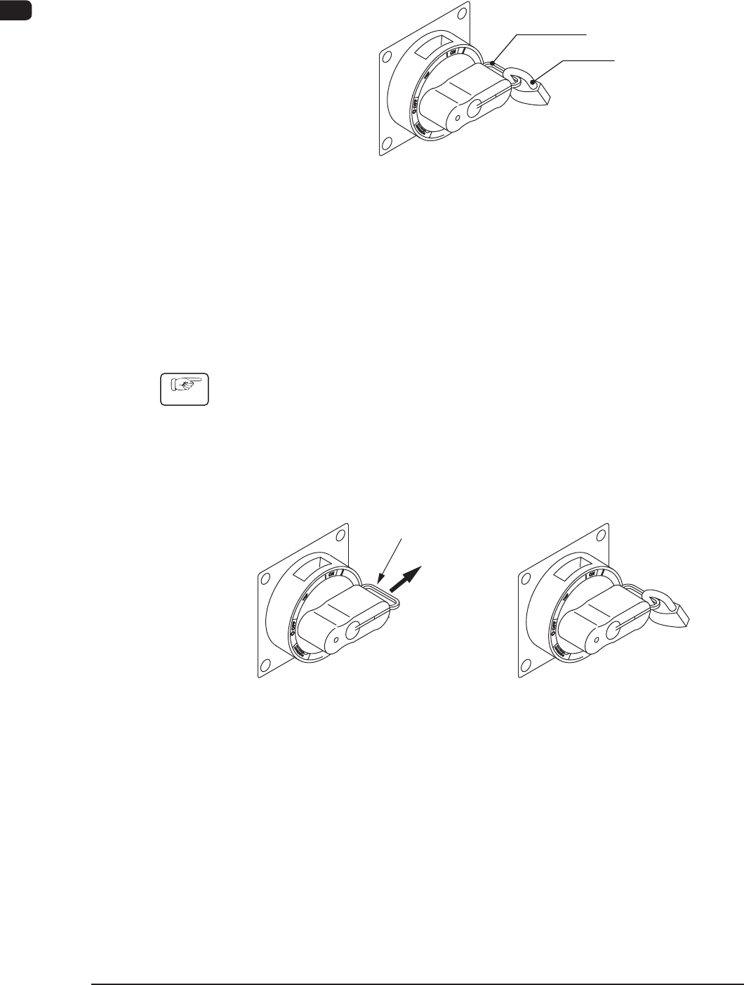
(1) Pull out the lock lever of the power breaker in Direction A (indicated in the
gure below).
Be sure not to release your hand from the lock lever. Otherwise, the lock
lever will pull back in place.
(2) Engage the shackle of the padlock through the lock slot and lock the crank.
(Unlocked) (Locked)
A
Lock Lever
F1A9
0906-001
1OM-1505
2. Names and Functions of Each Section : Chap.1
1-9
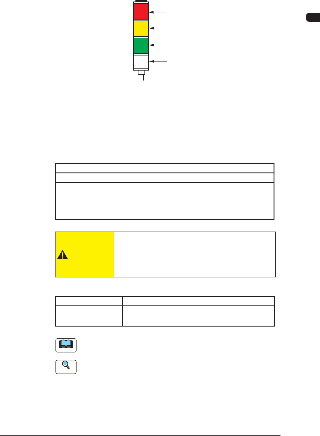
2.6 Light Tower
Red
Yellow
Green
Buzzer
Light Tower
F1A10
The light tower indicates the status of the machine with the lamps and buzzer
sounds.
•
Lamp Colors (ON Mode)
The machine is factory-adjusted upon shipment.
Lamp Colors (ON Mode) Machine Status
Red
Error (Operation Stopped)
Yellow
Component Shortage (Warning)
Green
Automatic Operation
When the machine is in the standby mode, this lamp
flickers.
T1A2
CAUTION
When the green lamp is ON or flickering (ON and OFF),
it indicates that the static machine is in the "Automatic"
mode (standby mode). Do not touch any moving areas of
the machine.
•
Buzzer
Buzzer Machine Status
Continuous Sound
Emergency Stop
Intermittent Sound
Error
T1A3
Note
The status of the machine corresponding to the parameters specied for each
lamp color and buzzer sound can be changed in the "MAC. SET-UP" window.
Reference
Refer to "5.1 Tower Lamp/Buzzer" in "Chapter 1 (Vol. 3)" for details.
0906-001
1OM-1505
1-10
2. Names and Functions of Each Section : Chap.1
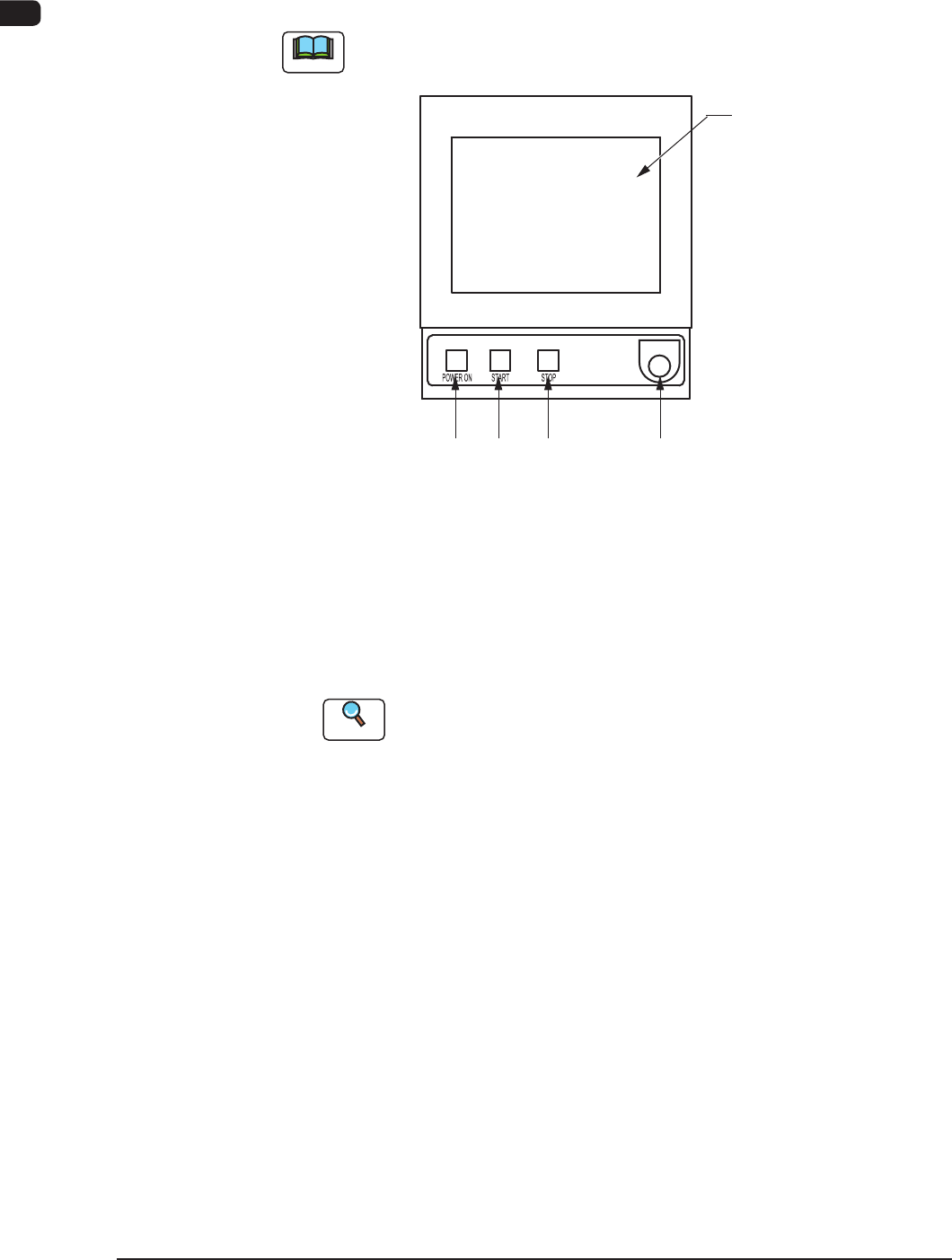
2.7 Operation Section
The touch screen and operation panel that are required to operate the machine, are
arranged on the main machine.
Note
The following operation buttons and switches are arranged in the operation
panel.
[2] [3] [4] [5]
[1]
Operation panel F1A11
[1] Touch Screen
The windows for operations are displayed on the touch screen.
Various operations can be performed by nger-touching the buttons that
appear on the screen.
Reference
Refer to "Short Appendix: Operation Panels and Touch Screens" for how
to handle the touch screens.
[2] [POWER ON] Button
Turning ON or OFF this button supplies or intercepts the power for
operations.
When the [POWER ON] button is pressed and the power for operations is
supplied, the LED of the [START] button flickers.
[3] [START] Button
When the [START] button is pressed while the lamp is fl
ickering after the
machine is powered, the automatic operation starts and the LED of the button
turns green.
While the LED is ON, it indicates that the automatic operation is being
performed.
When the [STOP] button is pressed during the automatic operation, the
automatic operation stops temporarily and the lamp of the [START] button
extinguishes.
While each device is being zeroed, the LED is kept ON.
1002-002