1OM-1505-004_w.pdf - 第76页
1OM-1505 4. Screen Printing Procedure : Chap.1 1-21 0906-001 4.1 PCB T ransfer and Positioning PCB PCB Detection Sensor on Input Side PCB Clamp T able PCB Stopper on Input Side PCB W arpage T op Holder PEC Recognition Ca…
1OM-1505
1-20
4. Screen Printing Procedure : Chap.1
0906-001
4. Screen Printing Procedure
The procedure for printing the PCB is described briefly.
PCB Input and Positioning 4.1
PEC Recognition 4.2
Printing 4.3
PCB Output 4.4
Printing Flow Chart F1A25
1OM-1505
4. Screen Printing Procedure : Chap.1
1-210906-001
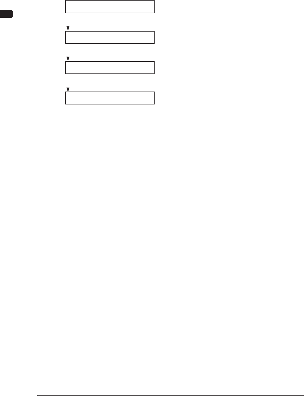
4.1 PCB Transfer and Positioning
PCB
PCB Detection Sensor on
Input Side
PCB Clamp
Table
PCB Stopper on
Input Side
PCB Warpage
Top Holder
PEC Recognition Camera
PCB Detection Sensor
PCB Stopper
PCB Backup Base
F1A26
(1) The PCB transferred from the input machine to the L conveyor is further
carried by the belt until it touches the PCB stopper on the input side. When
the PCB detection photosensor on the input side detects the PCB, the L
conveyor stops running.
(2) When the PEC recognition camera is moved to the position appropriate for
the PEC recognition size, the "PCB Stopper" is lowered.
(3) When the PCB stopper has moved down, the L conveyor is driven.
At this time, the PCB warpage top holder moves down.
(4) When the PCB is transferred to the PEC positioning section and pressed
against the "PCB Stopper" and the PCB is recognized using the "PCB
Detection Sensor", the L-conveyor and the conveyor in the PCB positioning
section, are stopped.
(5) The PCB backup base in the PCB positioning section
moves up and clamps
the PCB.
(6) When the actions in the PCB positioning section are completed, the PCB
warpage top holder and the PCB stopper move up.
1OM-1505
1-22
4. Screen Printing Procedure : Chap.1
0906-001
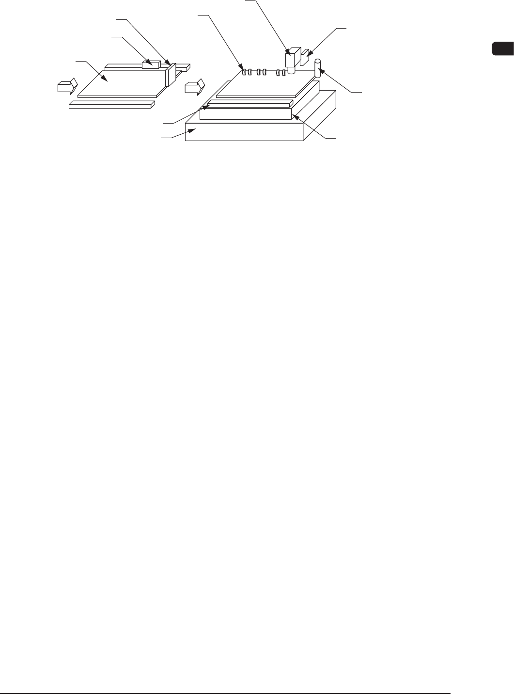
4.2 PEC Recognition
PCB
PEC Recognition Camera
Table
Stencil
F1A27
(1) The PEC recognition camera driving section moves in the X and Y directions
and recognizes two ducial marks. After the recognition, it is zeroed.
(2) The table Z-axis is lifted to the "Correction Movement Height".
(3) After the table has moved to the printing position, the location (coordinates)
of the table X and
θ
axis and the stencil Y axis is corrected as much as the
value calculated from the recognition results.
(4) The table Z axis moves up the table as far as the distance (gap) set up by the
pattern program data.