1OM-1505-004_w.pdf - 第79页
1OM-1505 1-24 4. Screen Printing Procedure : Chap.1 0906-001 4.4 PCB Output T able PCB Clamp PCB Passage Detection Sensor PCB Arrival Detection Sensor PCB Backup Base PCB F1A29 (1) The horizontal clamp releases the PCB a…
1OM-1505
4. Screen Printing Procedure : Chap.1
1-230906-001
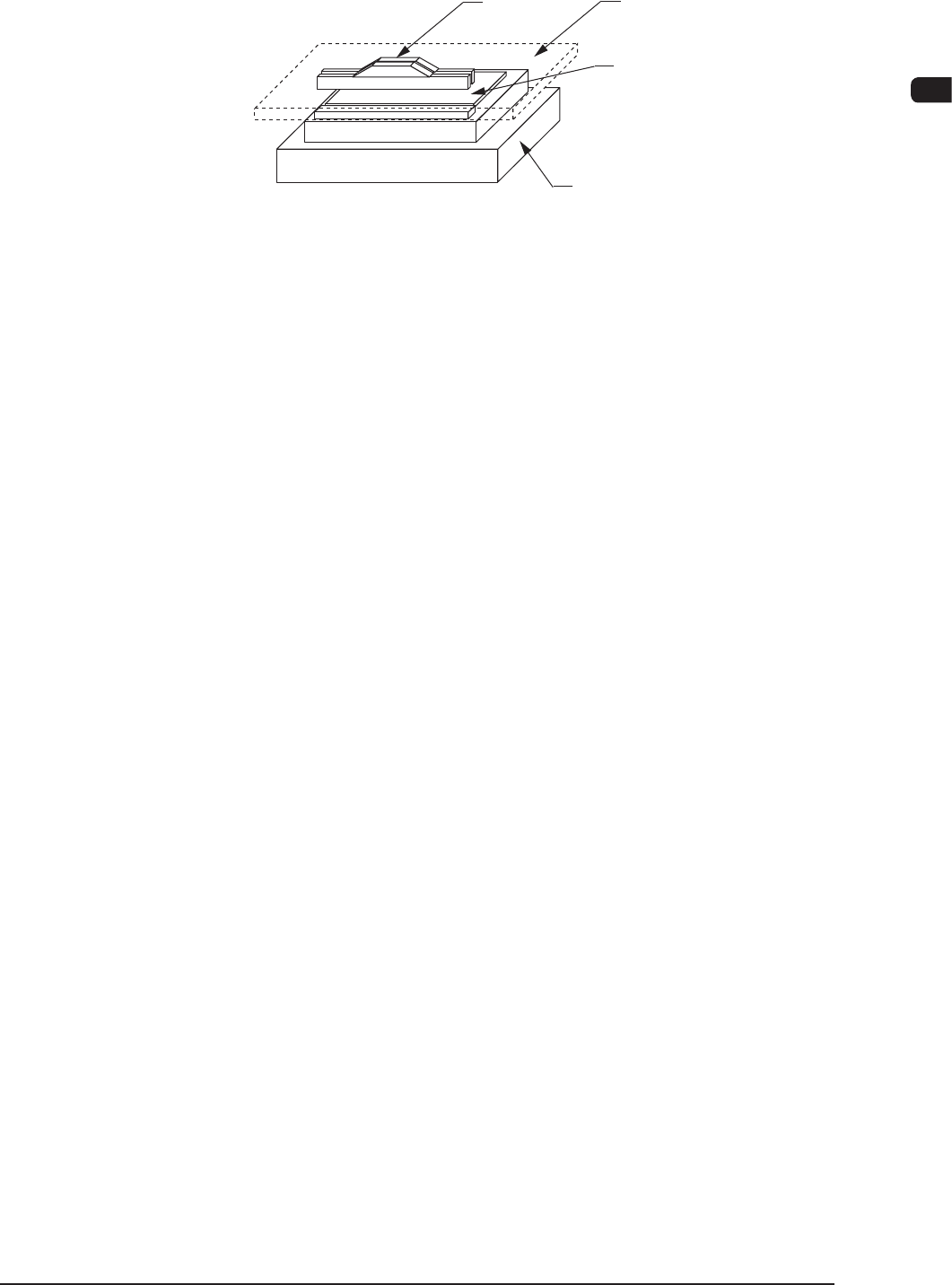
4.3 Printing
Squeegee
PCB
Table
Stencil
F1A28
(1) One-Way Printing
When the squeegees are located at the rear side of the printing stroke,
Squeegee B (rear) moves down and shifts to the front side for printing.
When the squeegees are located at the front side of the printing stroke,
Squeegee A (front) moves down and shifts to the rear side for printing.
Round-Way Printing
Squeegee A (front) moves down and shifts to the rear side. After printing, it
moves up at the rear side. Then, Squeegee B (rear) moves down and shifts to
the front side for printing.
(2)
After the squeegees are stopped and the table is lowered to the "Stencil
Separation Position" set in the "Pattern Program" window, the squeegees are
lifted.
(3) The table Z-axis is lowered to the "Correction Movement Height" and T
able
X-axis and
θ
-axis are moved to each home position.
(4) The table Z-axis is lowered to the PCB transfer height.
1OM-1505
1-24
4. Screen Printing Procedure : Chap.1
0906-001
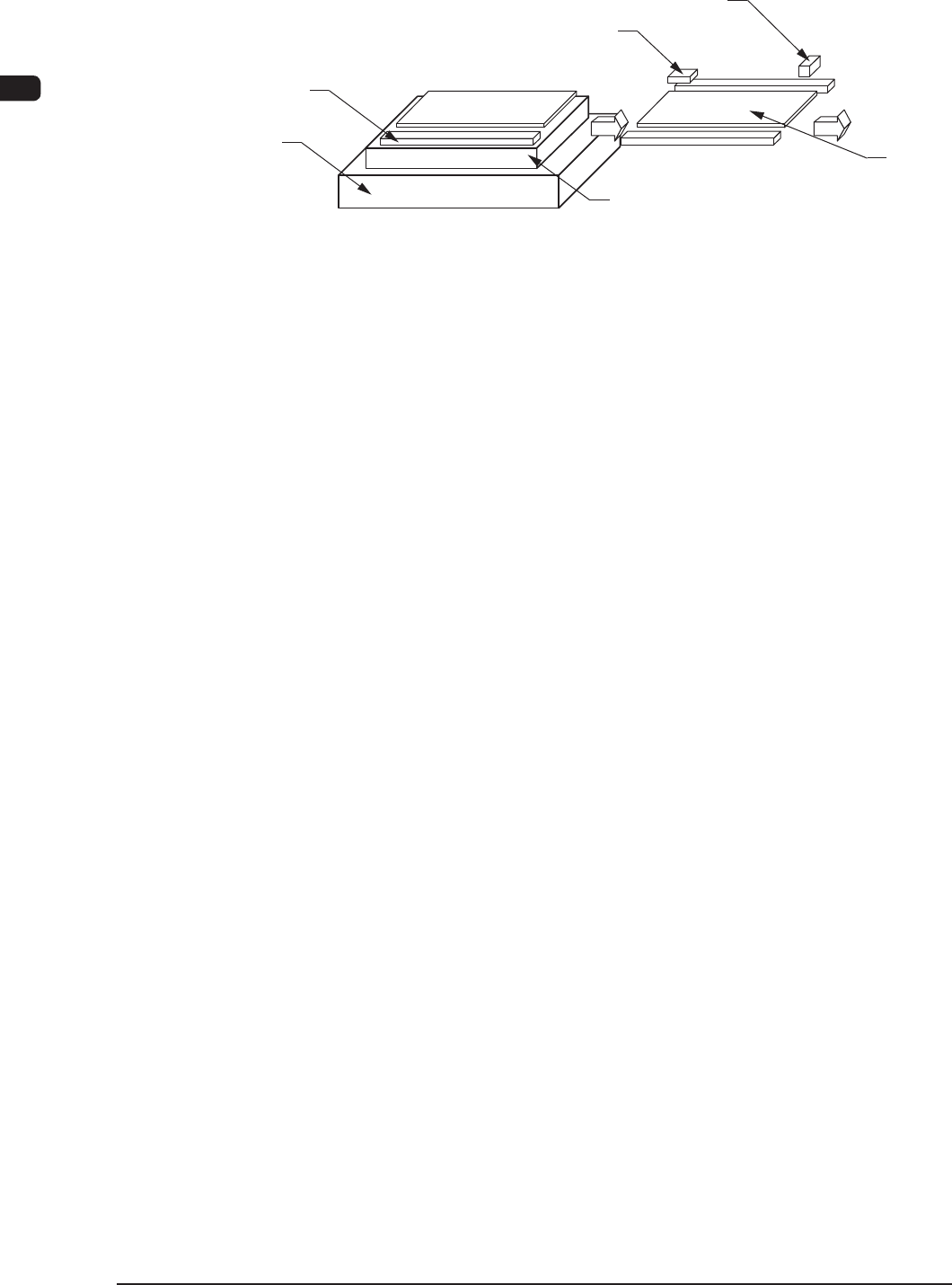
4.4 PCB Output
Table
PCB Clamp
PCB Passage Detection Sensor
PCB Arrival Detection Sensor
PCB Backup Base
PCB
F1A29
(1) The horizontal clamp releases the PCB at the PCB positioning section and
the PCB backup base moves down. Then, the PCB is transferred onto the
belt conveyor at the PCB positioning section.
(2) When the R-conveyor and the conveyor in the PCB positioning section
are driven and the condition that the PCB has been transferred onto the
R-conveyor using the "PCB Pass Detection Sensor" is conrmed, the
conveyor in the PCB positioning section is stopped.
(3) When the PCB arrival detection sensor detects the PCB, the R conveyor
stops running.
(4) When the machine receives a PCB request signal from the output machine,
the R conveyor is driven to transfer the PCB to the output machine.
(5) When the PCB request signal stops coming from the output machine, the R
conveyor also stops running.
1OM-1505
5. Various Functions : Chap.1
1-250906-001
5. Various Functions
5.1 Paste Kneading Function
Stable printing can be realized by mixing solder paste before printing, making
use of the rolling phenomenon of solder paste (solder paste stirred due to the
excessive flowing between the squeegee and the stencil).
Note
When the solder paste is already kneaded enough, this operation is not required.
Reference
Refer to "5.3 Paste Kneading" in "Chapter 3 (Vol.2)" for details.
5.2 Coordinate Teaching Function
This function is used to teach the PEC recognition mark position and stencil
recognition mark position coordinates.
The positional coordinates of two ducial marks can be taught in each recognition
mode.
Reference
Refer to "7.2 Coordinate" in "Chapter 3 (Vol.2)" for details.
5.3 Jig Position Coordinate Teaching Function
This function is used to teach the positional coordinates of the vacuum jig to pick
up and hold a PCB rmly.
Reference
Refer to "7.3 Vac. Jig Pos. Teaching" in "Chapter 3 (Vol.2)" for details.
5.4 Device Check and Management Functions
This function is used to display and manage the input conditions of various
sensors/motor control and software version information.
Reference
Refer to "3. DEVICE CHECK" in "Chapter 1 (Vol.3)" for details.