00192792-02.pdf - 第61页
SIPLACE 80 S-25 HM 2 Retrofitting Instructions: Matrix Tray Changer MTC on S-25 HM (Option) 01/01 Issue 2.6 Preparatory Steps 61 .H\ 1. Fastener s for the nozzle cha nger . 4 M4 socket h ex hea d cap sc rews M4 2. Elec…
2 Retrofitting Instructions: Matrix Tray Changer MTC on S-25 HM (Option) SIPLACE 80 S-25 HM
2.6 Preparatory Steps 01/01 Issue
60
.H\
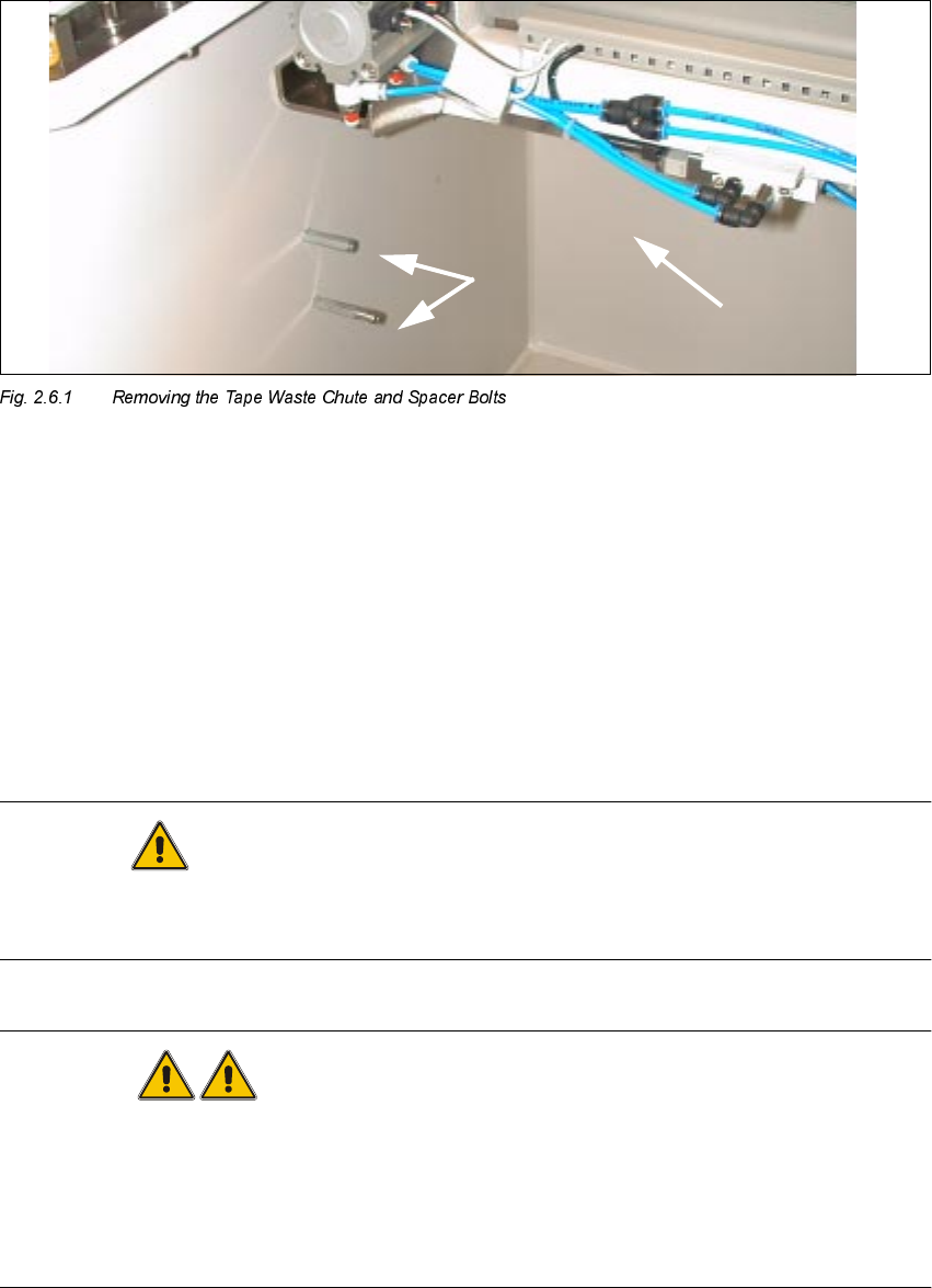
1. Tape waste chute (removed)
2. Remove 2 spacer bolts each, left and right
Å Remove the spacer bolts completely, 2 each on left and right (see Fig. 2.6.2).
Save the parts in such a manner that they will be available later for re-installation.
5HPRYLQJWKH+ROGH UIRU1R]]OH&KDQJHUD QG(PSW\ 7DSH'XFW
CAUTION
Make certain that no screws/small components drop into the cutter during the following disassem-
bly.
WARNING
After dismantling the empty-tape ducts - taking care to avoid injury, e.g., due to slipping - put a
wide piece of insulating tape on the top of the cutter, such that the gap between cover plate and
fixed blade is completely covered. This tape will be removed during a subsequent step.
In addition, during the retrofitting make shure that danger symbol and danger text are mounted on
the cover plate of the cutter (see Section 2.7.6).
SIPLACE 80 S-25 HM 2 Retrofitting Instructions: Matrix Tray Changer MTC on S-25 HM (Option)
01/01 Issue 2.6 Preparatory Steps
61
.H\
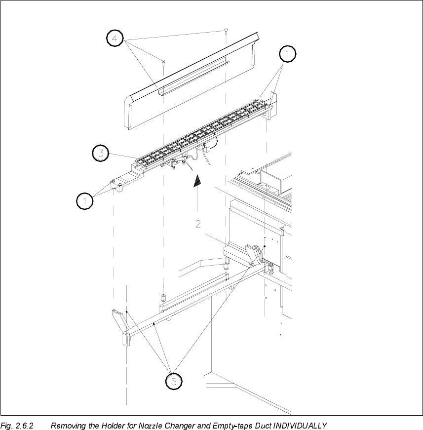
1. Fasteners for the nozzle changer. 4 M4 socket hex head cap screws M4
2. Electrical and pneumatic connection on the bottom of the nozzle changer
3. Nozzle changer
4. An empty-tape duct (is only dismantled as a complete unit)
Fastener: 2 socket hex head cap screws M4
5. Carrier for empty-tape duct and nozzle changer,
Fastened to the machine frame with 1 socket hex head cap screw M6 each, left and right
2 Retrofitting Instructions: Matrix Tray Changer MTC on S-25 HM (Option) SIPLACE 80 S-25 HM
2.6 Preparatory Steps 01/01 Issue
62
Å Undo the screws fastening the nozzle changer (4 socket hex head cap screws M4, Fig. 2.6.2)
and lift the changer a little.
Å On the bottom of the nozzle changer, loosen the electrical and pneumatic connections (see
Fig. 2.6.2) and take the nozzle changer out of the machine.
Å Dismantle the empty-tape duct (2 socket hex head cap screws M4).
Å Remove the carrier for nozzle changers (1 socket hex head cap screw M6 each, left and right:
see Fig. 2.6.2).
5HPRYLQJWKH&RYHU3ODWH'XVW&RYHU
.H\
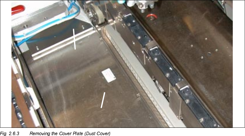
1. Long metal component; fasteners: 3 socket hex head cap screws M4
2. Side plate, left and right; fasteners: 2 socket hex head cap screws M3 each)
Å To guard against injury, place a wide adhesive strip over the gap between cover plate and fixed
blade along the entire length of the cutter.
Å Dismantle the cover plate (dust cover) in the area between the PCB conveyor and the compo-
nent feeder table (see Fig. 2.6.3).
If old machines are involved, this part may be made of black plastic.
To dismantle the cover plate:
Å Loosen the screws fastening the RH side panel (2 socket hex head cap screws M3 with half
rounded head).