00192792-02.pdf - 第63页
SIPLACE 80 S-25 HM 2 Retrofitting Instructions: Matrix Tray Changer MTC on S-25 HM (Option) 01/01 Issue 2.6 Preparatory Steps 63 Å Dismantle t he LH s ide panel (2 so cket hex head c ap screws M3) becau se yo u will no t…
2 Retrofitting Instructions: Matrix Tray Changer MTC on S-25 HM (Option) SIPLACE 80 S-25 HM
2.6 Preparatory Steps 01/01 Issue
62
Å Undo the screws fastening the nozzle changer (4 socket hex head cap screws M4, Fig. 2.6.2)
and lift the changer a little.
Å On the bottom of the nozzle changer, loosen the electrical and pneumatic connections (see
Fig. 2.6.2) and take the nozzle changer out of the machine.
Å Dismantle the empty-tape duct (2 socket hex head cap screws M4).
Å Remove the carrier for nozzle changers (1 socket hex head cap screw M6 each, left and right:
see Fig. 2.6.2).
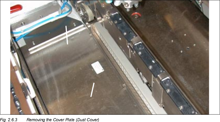
5HPRYLQJWKH&RYHU3ODWH'XVW&RYHU
.H\
1. Long metal component; fasteners: 3 socket hex head cap screws M4
2. Side plate, left and right; fasteners: 2 socket hex head cap screws M3 each)
Å To guard against injury, place a wide adhesive strip over the gap between cover plate and fixed
blade along the entire length of the cutter.
Å Dismantle the cover plate (dust cover) in the area between the PCB conveyor and the compo-
nent feeder table (see Fig. 2.6.3).
If old machines are involved, this part may be made of black plastic.
To dismantle the cover plate:
Å Loosen the screws fastening the RH side panel (2 socket hex head cap screws M3 with half
rounded head).
SIPLACE 80 S-25 HM 2 Retrofitting Instructions: Matrix Tray Changer MTC on S-25 HM (Option)
01/01 Issue 2.6 Preparatory Steps
63
Å Dismantle the LH side panel (2 socket hex head cap screws M3) because you will not be
able to take out the large panel otherwise.
Å Then loosen the screws fastening the long metal component to the machine frame (3 socket
hex head cap screws M4). The cover plate will not be re-used.
Å With the exception of the cover plate, keep ALL of the parts removed up to this point because
they may be needed for subsequent re-installation.
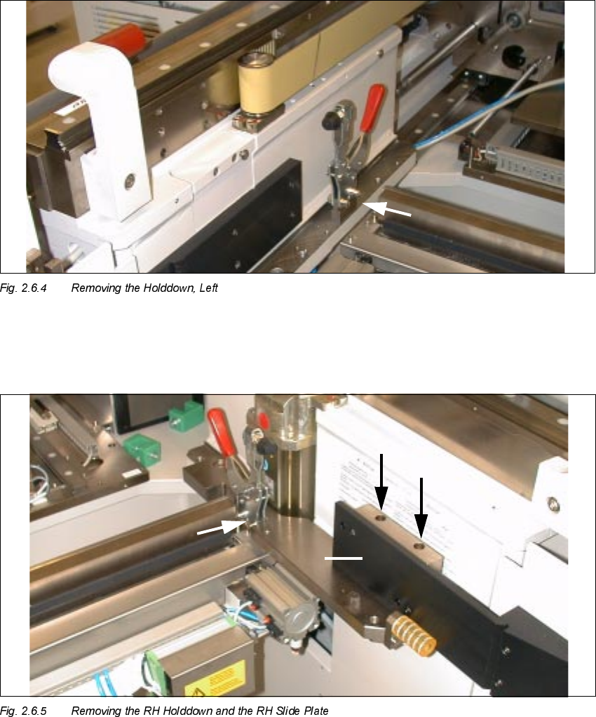
Å On the LH side, loosen the screws fastening the component table holddowns on the "Rail, com-
ponent table" (2 x socket hex head cap screws M6, size 5) and remove the holddown (see Fig.
2.6.4). The holddown will be needed for later re-installation.
2 Retrofitting Instructions: Matrix Tray Changer MTC on S-25 HM (Option) SIPLACE 80 S-25 HM
2.6 Preparatory Steps 01/01 Issue
64
.H\WR)LJVHHERWWRPOHIW
1. Holddown, RH side, to removed
2. Slide plate, RH side, to removed
3. Screws fastening the slide plate: 2 socket hex head cap screws M6 x 70
Å Dismantle the RH slide plate (black plastic component) from the machine frame
(2 socket hex head cap screws M6, size 5), as shown above.
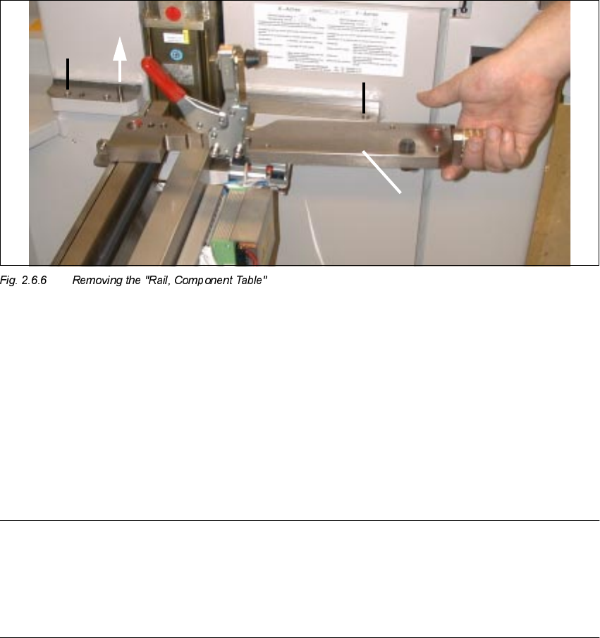
.H\
1. Screws fastening the "Rail, component table": 2 socket hex head cap screws M10 x 25
2. Direction in which "Rail, component table" is removed
3. "Rail, component table", removed
Å Dismantle the "Rail, component table" on the RH side of the machine frame (loosen the 2
socket hex head cap screws M10, size 8) and lift the plate off the centering pin.
NOTE:
The "Rail, component table" is exchanged for the new "Rail, component table" with RELIEF
MILLING NUT, Item no. 00334697-03 (see Fig. 2.7.2).
This means that the holddown, buffer and centering piece must be moved onto the new "Rail,
component table" as described below in Section 2.7.1.