00192792-02.pdf - 第65页
SIPLACE 80 S-25 HM 2 Retrofitting Instructions: Matrix Tray Changer MTC on S-25 HM (Option) 01/01 Issue 2.7 Installing the Retrofit Kit 65 ,QVW DOOLQJWKH5HWURILW.LW W ARNING Follow the s afety in structi ons for t…
2 Retrofitting Instructions: Matrix Tray Changer MTC on S-25 HM (Option) SIPLACE 80 S-25 HM
2.6 Preparatory Steps 01/01 Issue
64
.H\WR)LJVHHERWWRPOHIW
1. Holddown, RH side, to removed
2. Slide plate, RH side, to removed
3. Screws fastening the slide plate: 2 socket hex head cap screws M6 x 70
Å Dismantle the RH slide plate (black plastic component) from the machine frame
(2 socket hex head cap screws M6, size 5), as shown above.
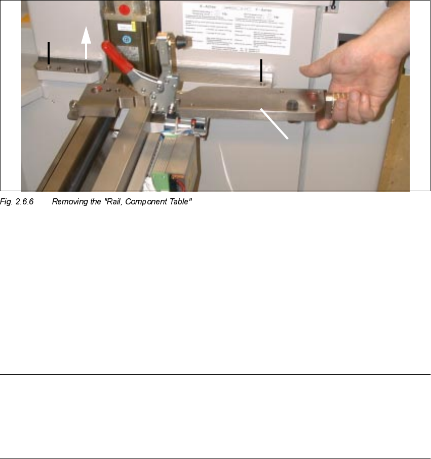
.H\
1. Screws fastening the "Rail, component table": 2 socket hex head cap screws M10 x 25
2. Direction in which "Rail, component table" is removed
3. "Rail, component table", removed
Å Dismantle the "Rail, component table" on the RH side of the machine frame (loosen the 2
socket hex head cap screws M10, size 8) and lift the plate off the centering pin.
NOTE:
The "Rail, component table" is exchanged for the new "Rail, component table" with RELIEF
MILLING NUT, Item no. 00334697-03 (see Fig. 2.7.2).
This means that the holddown, buffer and centering piece must be moved onto the new "Rail,
component table" as described below in Section 2.7.1.
SIPLACE 80 S-25 HM 2 Retrofitting Instructions: Matrix Tray Changer MTC on S-25 HM (Option)
01/01 Issue 2.7 Installing the Retrofit Kit
65
,QVWDOOLQJWKH5HWURILW.LW
WARNING
Follow the safety instructions for the cutter (see Section 2.6).
$VVHPEOLQJWKH5DLO&RPSRQHQW7DEOH
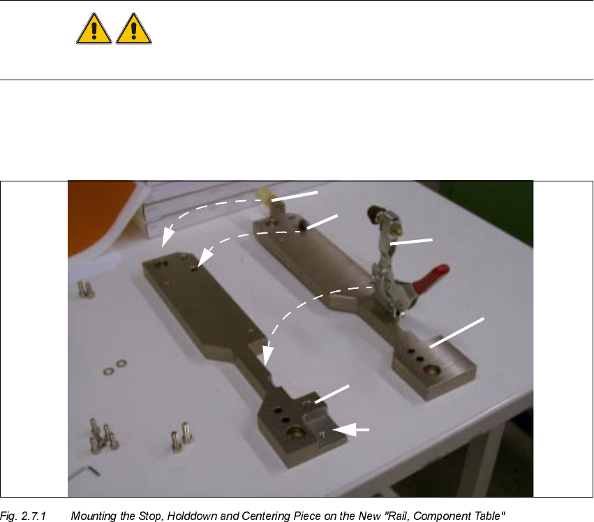
.H\
1. New "Rail, component table"
2. Relief milling cut
3. Old, "Rail, component table" after removal
4. Moving stop of the component table
5. Moving the holddown
6. Moving the centering piece (see also Detail, Fig. 2.7.2)
2 Retrofitting Instructions: Matrix Tray Changer MTC on S-25 HM (Option) SIPLACE 80 S-25 HM
2.7 Installing the Retrofit Kit 01/01 Issue
66
Å Dismantle the component table stop from the dismantled "Rail, component table" (undo 2
socket hex head cap screws M4).
Å Mount the stop on the new "Rail, component table" from the MTC retrofit kit (Item no.
00334697-03), see Fig. 2.7.1.
Å Dismantle the holddown (2 socket hex head cap screws M6) and fasten it to the new "Rail,
component table".
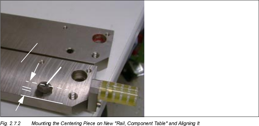
.H\
1. New "Rail, component table"
2. Centering piece (moved from the old "Rail, component table")
Å Loosen the locknut holding the centering piece (use fork wrench, size 13) and use a nylon
hammer to drive out the centering piece.
Å Insert the centering piece into the new "Rail, component table", align it with the longitudinal
edge parallel to the longitudinal edge of the "Rail, component table" (see Fig. 2.7.2) and fix the
centering piece in place with a locknut.
Å Apply screw-locking compound RED to the hex nut.