00192792-02.pdf - 第70页
2 Retrofitting Instructions: M atrix Tray Changer MTC on S-25 HM (Option) SIPLACE 80 S-25 HM 2.7 Installing t he Retrofit Kit 01/01 Issue 70 .H\ 1. 2 socke t hex h ead cap s crew s M6 2. 1 soc ket hex h ead cap s crew M…
SIPLACE 80 S-25 HM 2 Retrofitting Instructions: Matrix Tray Changer MTC on S-25 HM (Option)
01/01 Issue 2.7 Installing the Retrofit Kit
69
WARNUNG
To protect against manipulation which will cause material damage: As a final step, apply the
screw-locking compound RED to the two screws used to fasten the "Rail, component table".
Å Mount the slide rail, RH (black plastic part) with the 2 socket hex head cap screws M6 (size 5)
as shown in Fig. 2.6.5.
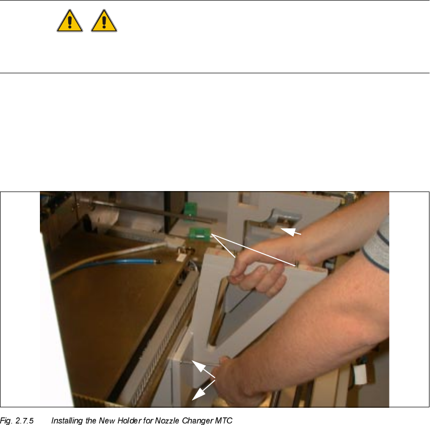
0RXQWLQJDQG$OLJQLQJWKH1HZ+ROGHUIRU1R]]OH&KDQJHU07&
.H\
1. Screws fastening the holder for the nozzle changer MTC:
3 socket hex head cap screws M6
2. 2 centering pins (already mounted)
Å Now mount the new holder for the nozzle changer MTC from the retrofit kit, Item no.
00357127-01:
Hold the holder against the machine frame (the RH link is resting on the frame) as shown
above and tighten the holder securely with the 3 socket hex head cap screws M6 (size 5).
The two parallel pins m6x6 are already inserted.
2 Retrofitting Instructions: Matrix Tray Changer MTC on S-25 HM (Option) SIPLACE 80 S-25 HM
2.7 Installing the Retrofit Kit 01/01 Issue
70
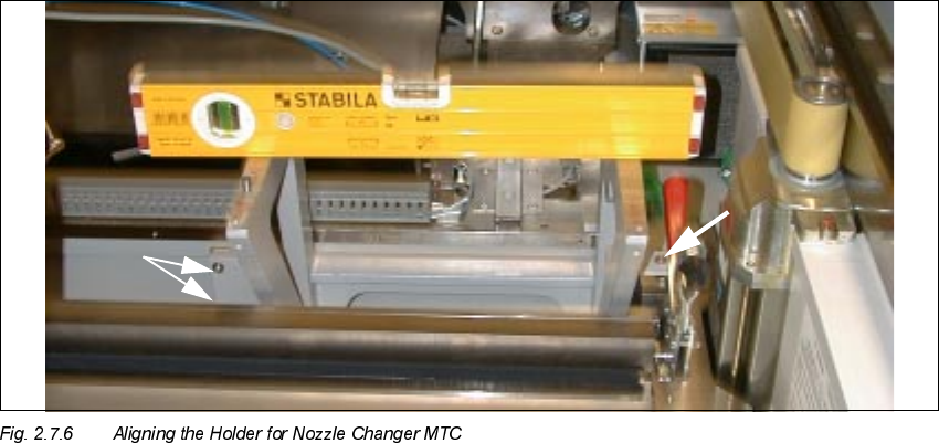
.H\
1. 2 socket hex head cap screws M6
2. 1 socket hex head cap screw M6 on support link
Å Place the spirit level on the contact surface of the carrier for the nozzle changer MTC, as shown
above.
Å If necessary, loosen the fastening screws again and use the spirit level to align the holder for
nozzle changer MTC:
With the holder in this position, first tighten the 2 screws (see Fig. 2.7.6 -> Pos. 1) and then the
screw for Pos. 2.
SIPLACE 80 S-25 HM 2 Retrofitting Instructions: Matrix Tray Changer MTC on S-25 HM (Option)
01/01 Issue 2.7 Installing the Retrofit Kit
71
0RXQWLQJWKH1HZ 'XVW&RYHUD QG&ODPSLQJ6K HHW0H WDORQ/+DQG5+
.H\
1. New dust cover, Item no. 00356051-01 (complete, incl. clamping sheet metals)
2. Screws to fasten the dust cover (long metal part): 4 socket hex head cap screws M3
3. "Clamping sheet metal, right": Fastened with 2 socket hex head cap screws M3.
Mount the "Clamping sheet metal, left" on the RH side in a corresponding manner (not shown).
Å Use the new dust cover from the retrofit kit (Item no. 00356051-01) with 2 long slots for immers-
ing the nozzle changer holder and mount it as follows:
Å First remove the RH clamping sheet metal (shown from the installation position: see Fig.
2.7.7) from the new dust cover (2 socket hex head cap screws M3).
Å From the outside and bottom, insert the long part of the new dust cover in such a manner
that the vertical tubes of the nozzle changer holder dip into the slots (see Fig. 2.7.7 -> 1).
Å Fasten the LH clamping sheet metal to the machine frame with the 2 socket hex head cap
screws M3.
Å Fasten the side wall of the dust cover to the machine frame with the 4 socket hex head cap
screws M4 (see Fig. 2.7.3 -> 2).
Å Insert the RH clamping sheet metal (see Fig. 2.7.7 -> 3) from above. Use a magnetic Allen
wrench, size 2.5, to insert the two M3 screws. Tighten the (half rounded head) screws.