00192792-02.pdf - 第73页
SIPLACE 80 S-25 HM 2 Retrofitting Instructions: Matrix Tray Changer MTC on S-25 HM (Option) 01/01 Issue 2.7 Installing the Retrofit Kit 73 .H\ 1. New nozzle change r MTC for 12-s egment head 2. Electric al and pneuma…
2 Retrofitting Instructions: Matrix Tray Changer MTC on S-25 HM (Option) SIPLACE 80 S-25 HM
2.7 Installing the Retrofit Kit 01/01 Issue
72
,QVWD OOLQJ1HZ1R]]OH&KDQJHU07&DQG6KRUW1HZ(PSW\7DSH'XF W
.H\
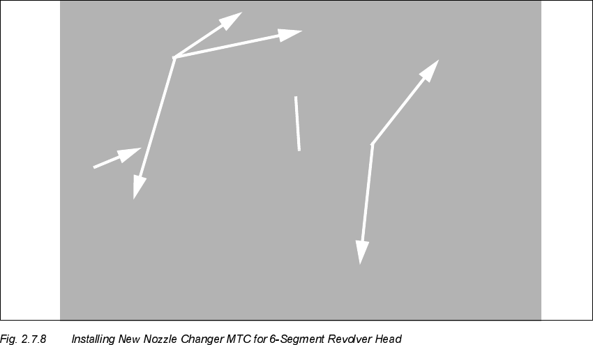
1. New nozzle changer MTC for 6-segment revolver head
2. Screws to fasten the nozzle changer: 5 socket hex head cap screws M5
3. Electrical and pneumatic connection of the nozzle changer MTC
(on the bottom of the nozzle changer)
SIPLACE 80 S-25 HM 2 Retrofitting Instructions: Matrix Tray Changer MTC on S-25 HM (Option)
01/01 Issue 2.7 Installing the Retrofit Kit
73
.H\
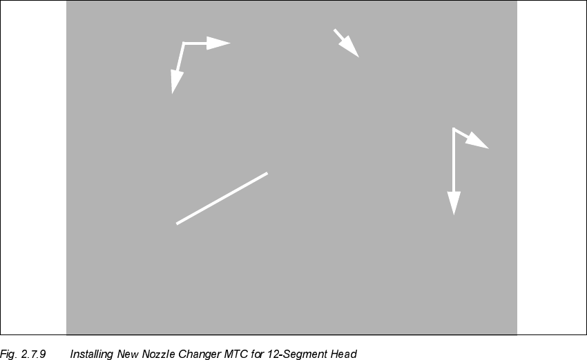
1. New nozzle changer MTC for 12-segment head
2. Electrical and pneumatic connection of the nozzle changer MTC (on the bottom of the nozzle
changer)
3. Screws to fasten the nozzle changer: 5 socket hex head cap screws M5
Å Place the relevant new nozzle changer MTC from the retrofit kit (Item number: see Section 2.5)
on the carrier, supporting it such that it remains in position while you make the pneumatic and
electric connections of the nozzle changer MTC at the bottom.
Å Insert the relevant new nozzle changer MTC into the centering pins of the holder.
Å Tighten the screws holding the nozzle changer MTC (5 socket hex head cap screws M5), as
shown in Fig. 2.7.8 and Fig. 2.7.9.
2 Retrofitting Instructions: Matrix Tray Changer MTC on S-25 HM (Option) SIPLACE 80 S-25 HM
2.7 Installing the Retrofit Kit 01/01 Issue
74
.H\
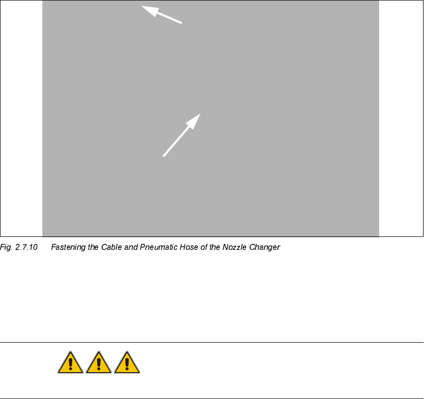
1. Self-adhesive mounting pedestal with cable tie
2. Cable tie
DANGER
NEVER clean with alcohol near an open light or flame.
Å Put the cover back on the cable duct (see Fig. above).
Å Use alcohol to degrease the area on which the self-adhesive mounting pedestal is to be placed
and mount the pedestal on it (position: see Fig. 2.7.10).
Å Run the cable and the pneumatic hose as shown and fasten them to the pedestal with a cable
tie.
,QVW DOOLQJWKH1HZ (PSW\7 DSH'XFWDQG+ROGHU
Å First make certain that the following warning signs are on the cover plate over the movable
blade. If not, install them (Item No.: see Section 2.5):
– Adhesive Label with text " Disconnect machine from mains voltage and....",
– Adhesive Label: Triangle warning symbol "Hand injury possible".