00192792-02.pdf - 第81页
SIPLACE 80 S-25 HM 2 Retrofitting Instructions: Matrix Tray Changer MTC on S-25 HM (Option) 01/01 Issue 2.7 Installing the Retrofit Kit 81 , QVW DOOLQJWKH&RPSRQHQW 5HMHFW%R[&RPSRQHQW7 DEOH Å Use the…
2 Retrofitting Instructions: Matrix Tray Changer MTC on S-25 HM (Option) SIPLACE 80 S-25 HM
2.7 Installing the Retrofit Kit 01/01 Issue
80
2. Remove the angle piece (will not be re-used)
3. Holddown: Not re-installed -> see earlier step in work sequence
Å Lift out the old component reject box that is on the left on the machine frame.
Å Remove the 2 socket hex head cap screws M4 (see Fig. 2.7.16).
The screws are glued in. Clean the remainder of the Loctite from the threads.
Å Place Loctite no. 243 on the threads: Tighten the two screws in the new positions in the ma-
chine frame.
Å Remove the inserted angle piece from the machine frame (undo 2 socket hex head cap screws
M5).
Retain the angle piece plus the 2 fastening screws and the reject box for possible re-installa-
tion.
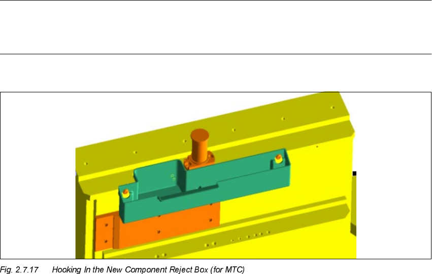
NOTE
Do not hook in the new component reject box MTC (see Fig. 2.7.17) until after the MTC has been
moved in (see Section 2.8.3, "Assembling the Machine").
Å The actual modification, i.e., the preparations for moving the MTC in, is now concluded.
SIPLACE 80 S-25 HM 2 Retrofitting Instructions: Matrix Tray Changer MTC on S-25 HM (Option)
01/01 Issue 2.7 Installing the Retrofit Kit
81
,QVWDOOLQJWKH&RPSRQHQW5HMHFW%R[&RPSRQHQW7DEOH
Å Use the "component reject box, table", Item no.: 00355146-01, if the machine frame doesn’t
have the opening for MTC (up to approximately serial number 449). Place this reject box - like
a feeder module - on the component table immediately to the right, perhaps not until after the
MTC has been moved in for the first time.
– The reject box requires the feeder locations of 3 feeder modules 2 x 8 mm.
– The "reject box component table" has to be configured later in SITEST (see: Section 2.8.5).

2 Retrofitting Instructions: Matrix Tray Changer MTC on S-25 HM (Option) SIPLACE 80 S-25 HM
2.8 Installing the MTC 01/01 Issue
82
,QVWDOOLQJWKH07&
DANGER:
Severe injury may result if the MTC is handled incorrectly.
Comply with ALL of the safety instructions in the "MTC User Manual" (Item no. 00192318-01).
Carry out all of the steps detailed in the section "Installing the MTC in the
SIPLACE Station" of the MTC User Manual.
Observe the DANGER texts regarding transport in the section "Assembling and Disassembling
the MTC" in the above-mentioned user manual. Under no circumstances is the MTC to be trans-
ported with a pallet truck; this might cause it to tip over.
6HWWLQJWKH+HLJKWDQG0RYLQJWKH07&,QIRUWKH)LUVW7LPH
Å Check the shock and position indicator on the MTC.
They must indicate that the MTC has been transported without error.
Å Check whether the MTC is already set to the required conveyor height.
The following HEIGHTS are possible (each with a tolerance of +10 / -15 mm):
– 950 mm
– 930 mm
– 900 mm
– 830 mm