DECAN_S2_Admin(Eng_Ver4.5).pdf - 第151页
6-38 Advanced Chip Shooter DECAN S2 Admi nistra t or’s Guide mark data is correct. W h en the test is successful, the following message box is displayed.. Caution If you move to another scree n while editing the “Board” …
6-37
Board Definition
Black: the mark appears darker than the surrounding.
White: the mark appears brighter than the surrounding.
<5. Search Area> group
Set the area to test the Accept Mark. The purpose is to limit the testing area when
recognition is interfered due to a shape similar to the mark near the mark.
<Width X> edit box
Set the range to test in X axis direction. In general, set to 6mm.
<Width Y> edit box
Set the range to test in Y axis direction. In general, set to 6mm.
<6. Mark Size> group
The size of the Accept Mark is displayed.
<Size X> edit box
The horizontal size of the Accept Mark is displayed. The size is changed based on
the value set in the <Width X> edit box of <5. Search Area> group.
<Size Y> edit box
The vertical size of the Accept Mark is displayed. The size is changed based on
the value set in the <Width Y> edit box of <5. Search Area> group.
<7. Parameter> group
<Threshold> edit box
The image viewed through the SM Vision window is composed of each pixel.
Each pixel has a unique value between 0 and 255 according to the seen degree of
brightness. Here, ‘Threshold Value’ indicates the border value deciding whether
each pixel should be recognized in white or black. That is, setup the limitation for
deciding if the image pixel should be black or white when checking a bad mark.
For example, if accept mark setup is “Black” and the <Threshold> value is 100, all
values under 100 in the vision image are recognized as black. And if <Accept
mark Logic> is “White” and the <Threshold> value is 100, all values over 100 in
the vision image are recognized as white.
<Real Display/Binary> button
Shows the image seen through the SMVision in real display to which threshold is
not applied, or in the image (Binary) to which threshold is applied as recognized
by MMI.
<Light> group
Set the lighting value when testing the Accept Mark. In general, set to 7. However,
adjust it properly according to the condition of the PCB and accept mark.
<Test> button
Tests the mark by using the set mark data. The user can check whether the set
6-38
Advanced Chip Shooter DECAN S2 Administrator’s Guide
mark data is correct. When the test is successful, the following message box is
displayed..
Caution If you move to another screen while editing the “Board”
dialog box, the edited data is saved automatically
<Update> button
Save the Accept Mark data and close the “Accept Mark Position” dialog box.
<Cancel> button
Close the “Accept Mark Position” dialog box without saving the Accept Mark data.
6-39
Board Definition
6.6. 2D Barcode
6.6.1. Configuration
Allows a user to know the model information of the PCB loaded into the machine by
recognizing the barcode on the PCB and manage the production history by PCB being
interlocked with the Lot Tracking System (LTS).
When using the 2D barcode
In the [Option] item of the “C:\SmartSM\bin\SmartSM.ini” file, set the IQFEEDER to
1 and the LotTracking to 2, Usebarcode to 1. Then press the ‘Barcode Position’ button
in the “Board Definition’ dialog box.
When using 1D barcode
In the [Option] item of the “C:\SmartSM\bin\SmartSM.ini” file, set the IQFEEDER to
1 and LotTracking to 1, Usebarcode to 0.
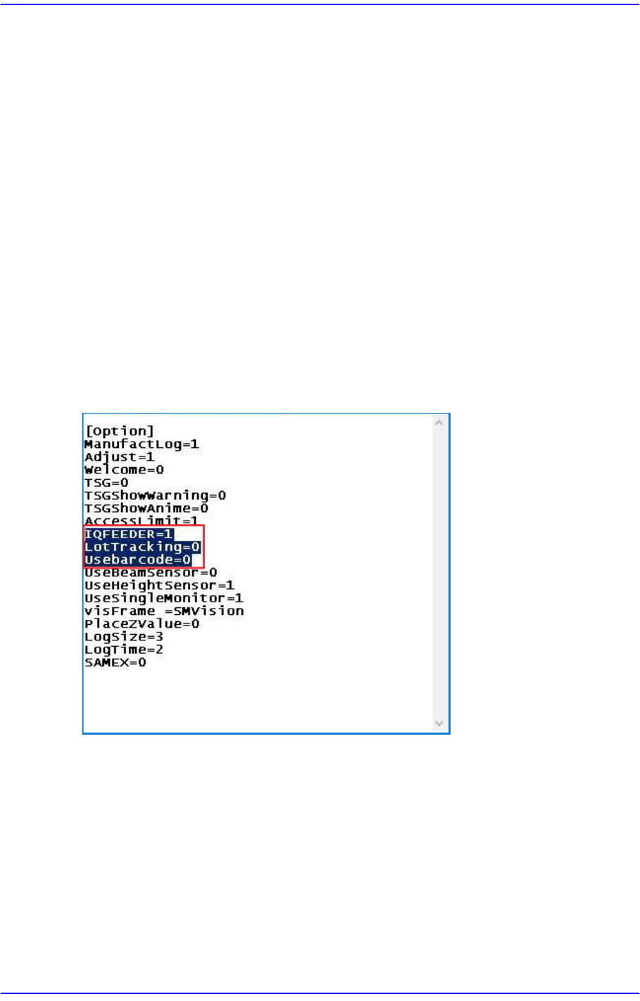
When using no barcode (When using IT Only)
In the [Option] item of the “C:\SmartSM\bin\SmartSM.ini” file, set the IQFEEDER to
1 and LotTracking to 0, Usebarcode to 0.
After finishing the modification of the configuration file, execute the “SmartSM.exe”.