DECAN_S2_Admin(Eng_Ver4.5).pdf - 第181页
7-16 Advanced Chip Shooter DECAN S2 Admi nistra t or’s Guide Memo In the case of the QFP for fine pitch parts, when the Z-axis moves down at high speed to place the part, it may physically collide with the PCB. In additi…
7-15
Part Registration
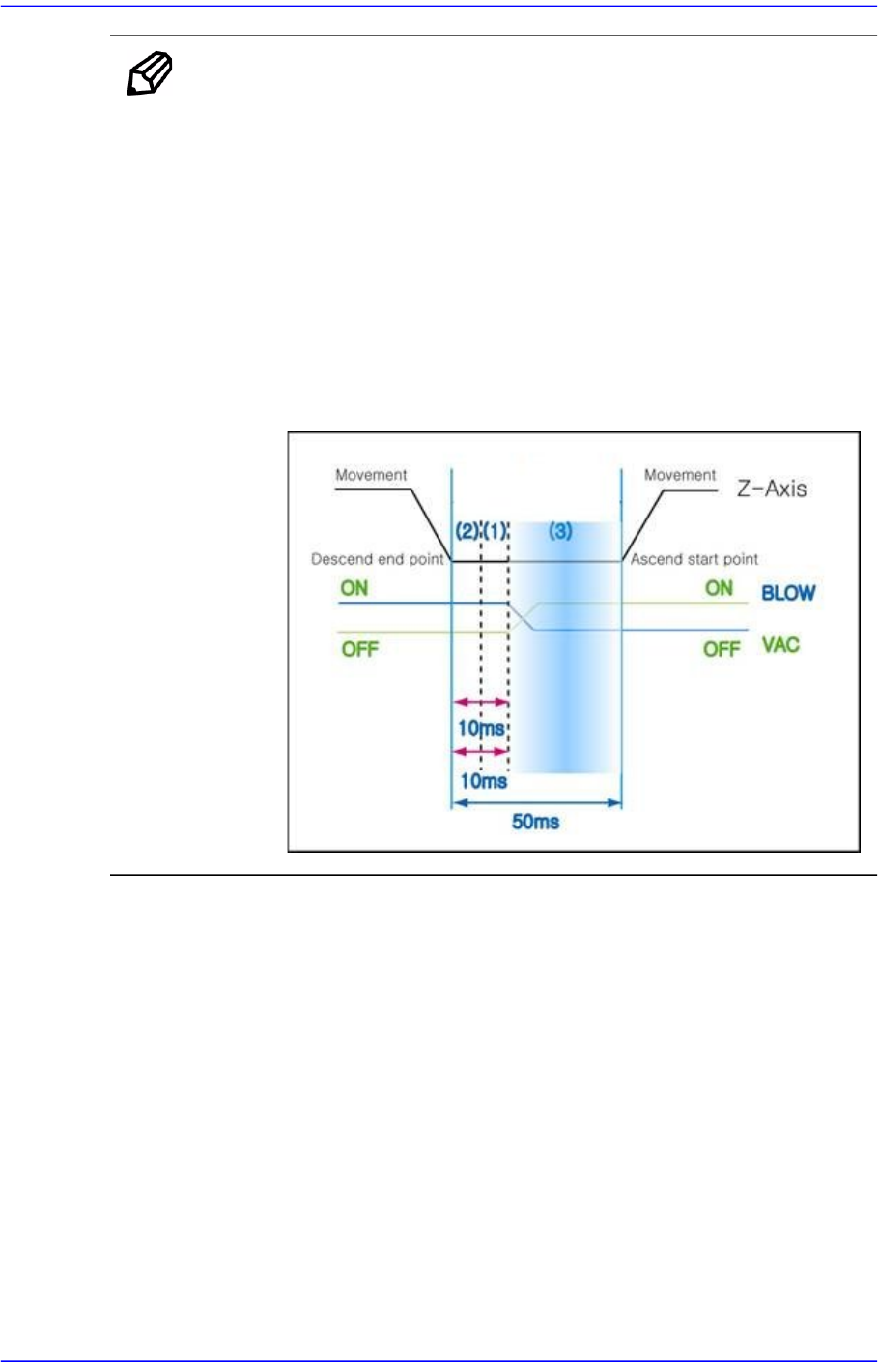
Memo Normally, the type of the time graph becomes different by parts.
For example, in the case of the general rectangular chips greater
than 1608, the parts are very light. Therefore, if the Z-axis moves
up before the vacuum disappears completely, the part may fall to
the PCB when the vacuum disappears while it moves up along
with the head.
In other words, item (3) in the following figure may act as the most
important factor for general rectangular chips.
From many test and experiment results, it was known that the
required time in item (3) was at least 0ms up to 20ms. Since this is
very important, the user must have this in mind.
7-16
Advanced Chip Shooter DECAN S2 Administrator’s Guide
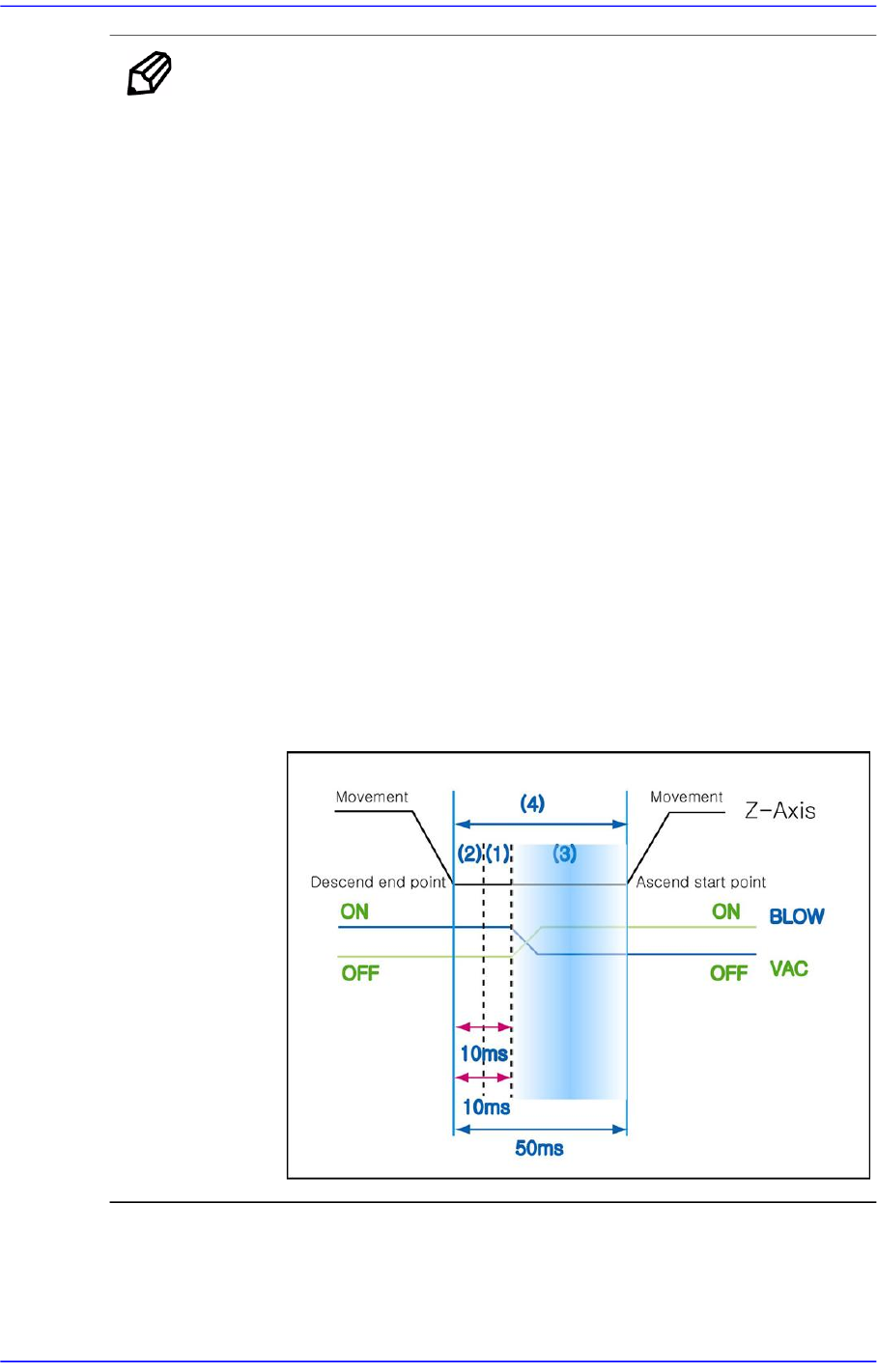
Memo In the case of the QFP for fine pitch parts, when the Z-axis moves
down at high speed to place the part, it may physically collide with
the PCB.
In addition, such impact may shake the PCB slightly and cause the
solder paste to be mashed. Therefore, placing the parts in this manner
may cause the reduction of placement accuracy.
Such situation can be prevented by controlling the Vac off delay time.
That is, the part is held by a vacuum until various external factors are
stabilized, after which the vacuum is turned off after the external
factors disappear to prevent the problem.
The Vac off delay time corresponds to item (1) of the following
figure.
In the case of parts with general pitch, even though the time in the
above item (1) is not considered, it does not have great influence on
the placement accuracy.
However, in the case of parts with fine pitch or those that may cause
the above problem, it may be beneficial to set the time in item (1)
short.
Generally, the Vac off delay time is set to 20~30% of the total delay
time in item (4). Since this is very important, the user must have
this in mind.
<Dump> edit box
During component dumping, the delay time after the head has come down
until the head starts ascending.

7-17
Part Registration
<Dump Vac Off> edit box
During component dumping, the delay time after the head has come down
until vacuum off.
<Dump Blow On> edit box
During component dumping, The time from vacuum off till blown on
once the head stops upon completion of descent.
Unit: msec (Possible to setup for 10 msec intervals)
<Speed> group
Set the speed for each axis during pickups, placement, and dumping operations.
The speed must be set appropriately according to the corresponding part by
considering the nozzle type, part weight, pickup area of the part, etc
The speeds are as follows, and the profile of each moving speed is set in the
system.
1- Fastest: The fastest speed.
2- Fast: Fast speed.
3- Middle: Middle speed.
4- Slow: Slow speed.
5- Slowest: The slowest speed.
<XY> combo box
Select the driving speed of the XY axis driving motor. If the speed is
inappropriate according to the part, A part may jump during pickup, causing a
pickup error.
<Z Pick Down> combo box
Select driving speed of the Z-axis driving motor while the head is descending
to pickup parts. If the speed is inappropriate according to the part, the part
may jump, causing a pickup error.
The “Soft Touch” function can be used together, if needed.
<Z Pick Up> combo box
Select driving speed of the Z-axis driving motor while the head is ascending to
pickup parts. If the speed is inappropriate according to the part, the part may
drop from the nozzle, causing a pickup error.
The “Soft Touch” function can be used together, if needed.
<R> combo box
Select the driving speed of the R axis driving motor. If the speed is
inappropriate according to the part, the part may be slipped so that the angle of
the part may be distorted or it may drop off.