DECAN_S2_Admin(Eng_Ver4.5).pdf - 第214页
7-49 Part Registration Selected to use t h e function t hat checks the turnover of the LED.For mo re detail s , refer the “<Use LED flip check> Che ck Box” of “7.1.2.2 CHIP-R e ct Part Data Setup” . Set the align o…
7-48
Advanced Chip Shooter DECAN S2 Administrator’s Guide
7.1.2.3. Melf component data setting
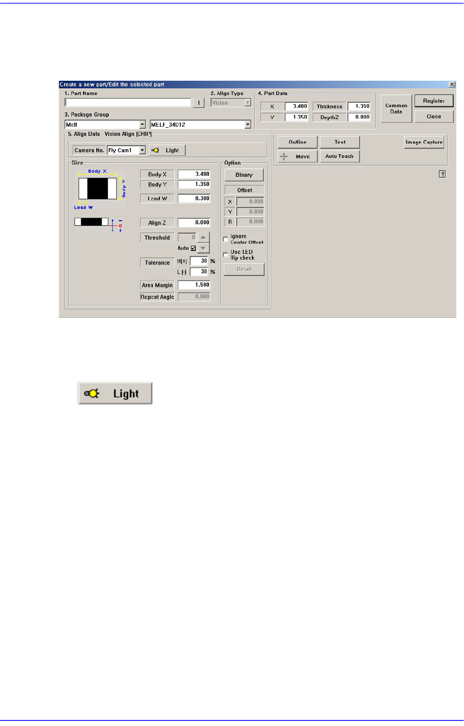
Set the align data for Melf components.
Figure7.15 “Package Group =Melf” dialog box
<Camera No.> combo box
Select the camera to recognize the component. Please refer to“7.1.1 Common Align
Data” for more information.
button
Select the light for the camera to recognize the component. Please refer to “7.1.1
Common Align Data” for more information.
<Size> group
Set the align size.
<Body X> edit box
Set the component size in X direction.
<Body Y> edit box
Set the component size in Y direction.
<Lead W> edit box
Set the length of lead in X direction.
For other setups, please refer to ““7.1.1 Common Align Data”.
<Option> group
Set the Align Option data.
<Use LED flip check> check box

7-49
Part Registration
Selected to use the function that checks the turnover of the LED.For more details,
refer the “<Use LED flip check> Check Box” of “7.1.2.2 CHIP-Rect Part Data
Setup”.
Set the align option data. Please refer to“7.1.1 Common Align Data” for more
information.
<Move> button
Performs component pickups or moves to the fix camera. Please refer to“7.1.1
Common Align Data” for more information.
<Test> button
Tests component recognition by using the set align data. Please refer to “7.1.1
Common Align Data” for more information.
<Image Capture> button
Helps to specify the optimum lighting value. The lighting is gradually changed
automatically and the images are saved. The user can check the best image and
identify the optimum lighting value. Please refer to “7.1.1 Common Align Data” for
more information.
7-50
Advanced Chip Shooter DECAN S2 Administrator’s Guide
7.1.2.4. TR component data setting
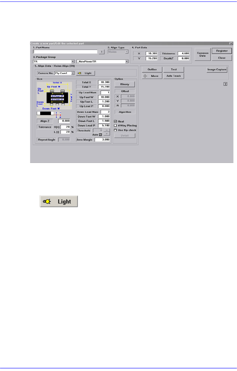
Set the align data for TR components.
Figure7.16 “Package Group =TR” dialog box
<Camera No.> combo box
Select the camera to recognize the component. Please refer to “7.1.1 Common Align
Data” for more information.
button
Set the light for the camera to recognize the component. Please refer to “7.1.1
Common Align Data” for more information.
<Size> group
Set the Align size.
<Total X> edit box
Set the component size in X direction.
<Total Y> edit box
Set the component size in Y direction.
<Up Lead Num> edit box
Set the number of upper leads.
<Up Foot W> edit box
Set the length of the upper lead foot in X direction.
<Up Foot L> edit box
Set the length of the upper lead foot in Y direction