DECAN_S2_Admin(Eng_Ver4.5).pdf - 第220页
7-55 Part Registration <Corner Check> butto n Even though th e shape of the part is rectangular , it is curved dif f erently compared to the shape of gen eral leads. There f ore, it is applied to a part that i s …
7-54
Advanced Chip Shooter DECAN S2 Administrator’s Guide
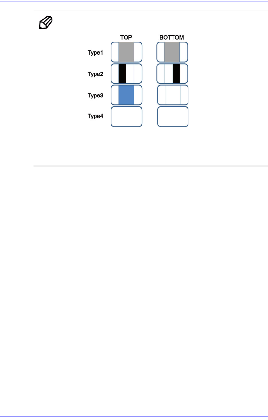
Memo In the following cases, the ‘flip check’ function cannot be used.
The top and bottom shapes of the part are the same.
The image of the top and bottom surfaces is not contrasted
clearly.
<Option> group
Set the align option data.
<Rough Check> check box
When recognizing a part, if a recognition error occurs because the shape of the
part to be recognized does not match with the vision algorithm data, select this
check box.
If this check box is selected, even if a certain shape of the part to be recognized is
more or less incorrect when compared with the vision algorithm data, the part is
recognized correctly in case it is identical when checking the layout of the entire
parts.
Please refer to “7.1.1 Common Align Data” for more information.
<Move> button
Performs component pickups or moves to the stage camera. Please refer to “7.1.1
Common Align Data” for more information.
<Test> button
Tests component recognition by using the set align data. Please refer to “7.1.1
Common Align Data” for more information.
<Image Capture> button
Helps to specify the optimum lighting value. The lighting is gradually changed
automatically and the images are saved. The user can check the best image and
identify the optimum lighting value. Please refer to“7.1.1 Common Align Data” for
more information.
7-55
Part Registration
<Corner Check> button
Even though the shape of the part is rectangular, it is curved differently compared to
the shape of general leads. Therefore, it is applied to a part that is difficult to register.
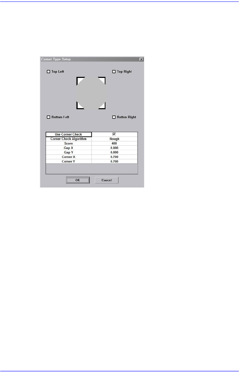
Clicking this button will display the following dialog box to set the corner type. Used
only for Trimmer parts
<Top Left set> check box
If the upper left corner of the part is a round shape with a bright colored pattern,
select this check box.
<Top Right set> check box
If the upper right corner of the part is a round shape with a bright colored pattern,
select this check box.
< Bottom Left set> check box
If the lower left corner of the part is a round shape with a bright colored pattern,
select this check box.
< Bottom Right set> check box
If the lower right corner of the part is a round shape with a bright colored pattern,
select this check box.
<Use Corner Check> check box
When using the <Use Corner Check> corner check algorithm, select this check
box.
<Corner Check Algorithm> check box
Select the vision algorithm to be used to perform the corner check.
7-56
Advanced Chip Shooter DECAN S2 Administrator’s Guide
Fine
The boundary of the corner is recognized precisely. It is recommended that
this method be selected.
Rough
The value for the boundary of the corner is not checked. It is not
recommended that this method be selected.
<Score> edit box
Enabled when the <Use Corner Check> is selected.
"Score” is the numerical value that indicates how accurately the recognized part
shape matches with the vision algorithm data selected from the <Corner Check
Algorithm> combo box when recognizing the part shape. This "Score” has a value
between 0 and 1000 points.
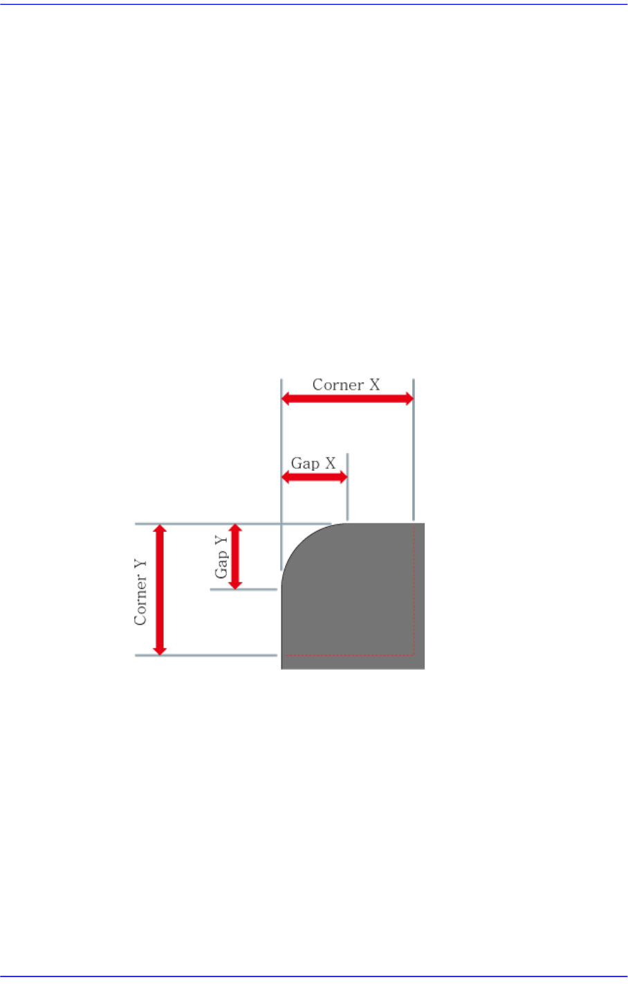
<Gap X/Y, Corner X/Y> edit box
The corner of the area to be recognized as X / Y direction size.
<Use flip check> Check box
Checks for part flip-over. For more details, please refer to "7.1.2.4. TR component
data setting". for more information.