DECAN_S2_Admin(Eng_Ver4.5).pdf - 第222页
7-57 Part Registration 7.1.3. IC component data setting 7.1.3.1. SOP/ SOJ/ SOP2/ SOJ2 component data setting Set the align data for SOP/ SOJ/ SOP2/ SOJ2 c omponents. Figure7.18 “P ackage Group =SOP ” dialog box Figure7.1…
7-56
Advanced Chip Shooter DECAN S2 Administrator’s Guide
Fine
The boundary of the corner is recognized precisely. It is recommended that
this method be selected.
Rough
The value for the boundary of the corner is not checked. It is not
recommended that this method be selected.
<Score> edit box
Enabled when the <Use Corner Check> is selected.
"Score” is the numerical value that indicates how accurately the recognized part
shape matches with the vision algorithm data selected from the <Corner Check
Algorithm> combo box when recognizing the part shape. This "Score” has a value
between 0 and 1000 points.
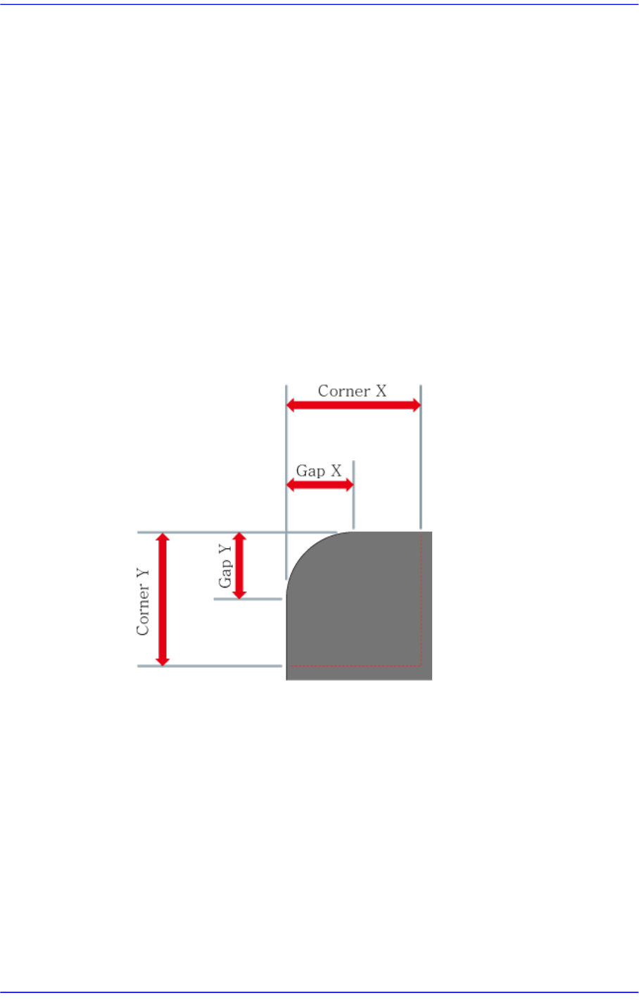
<Gap X/Y, Corner X/Y> edit box
The corner of the area to be recognized as X / Y direction size.
<Use flip check> Check box
Checks for part flip-over. For more details, please refer to "7.1.2.4. TR component
data setting". for more information.
7-57
Part Registration
7.1.3. IC component data setting
7.1.3.1. SOP/ SOJ/ SOP2/ SOJ2 component data setting
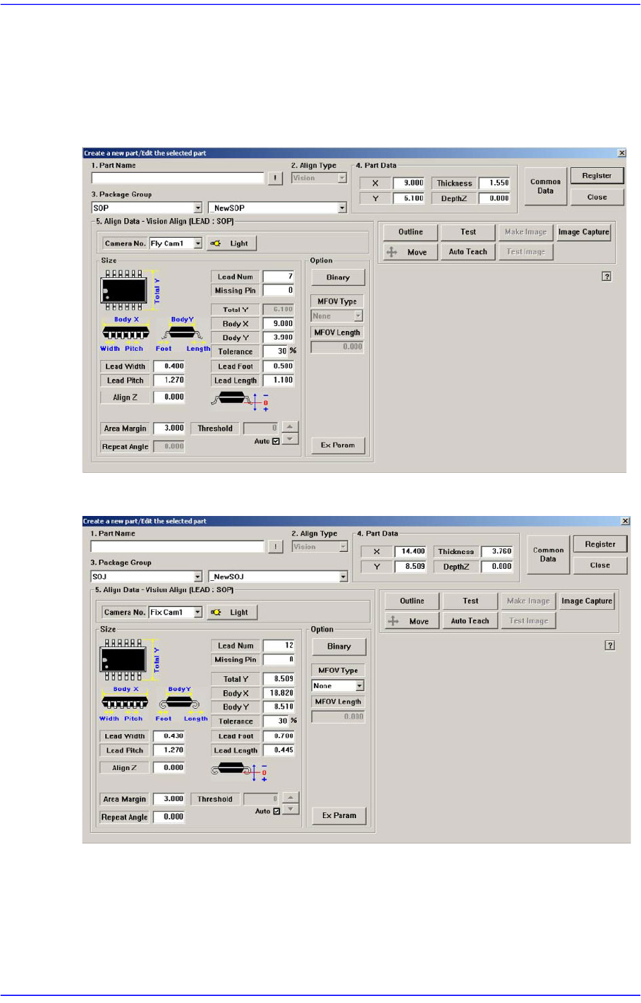
Set the align data for SOP/ SOJ/ SOP2/ SOJ2 components.
Figure7.18 “Package Group =SOP” dialog box
Figure7.19 “Package Group =SOJ” dialog box
7-58
Advanced Chip Shooter DECAN S2 Administrator’s Guide
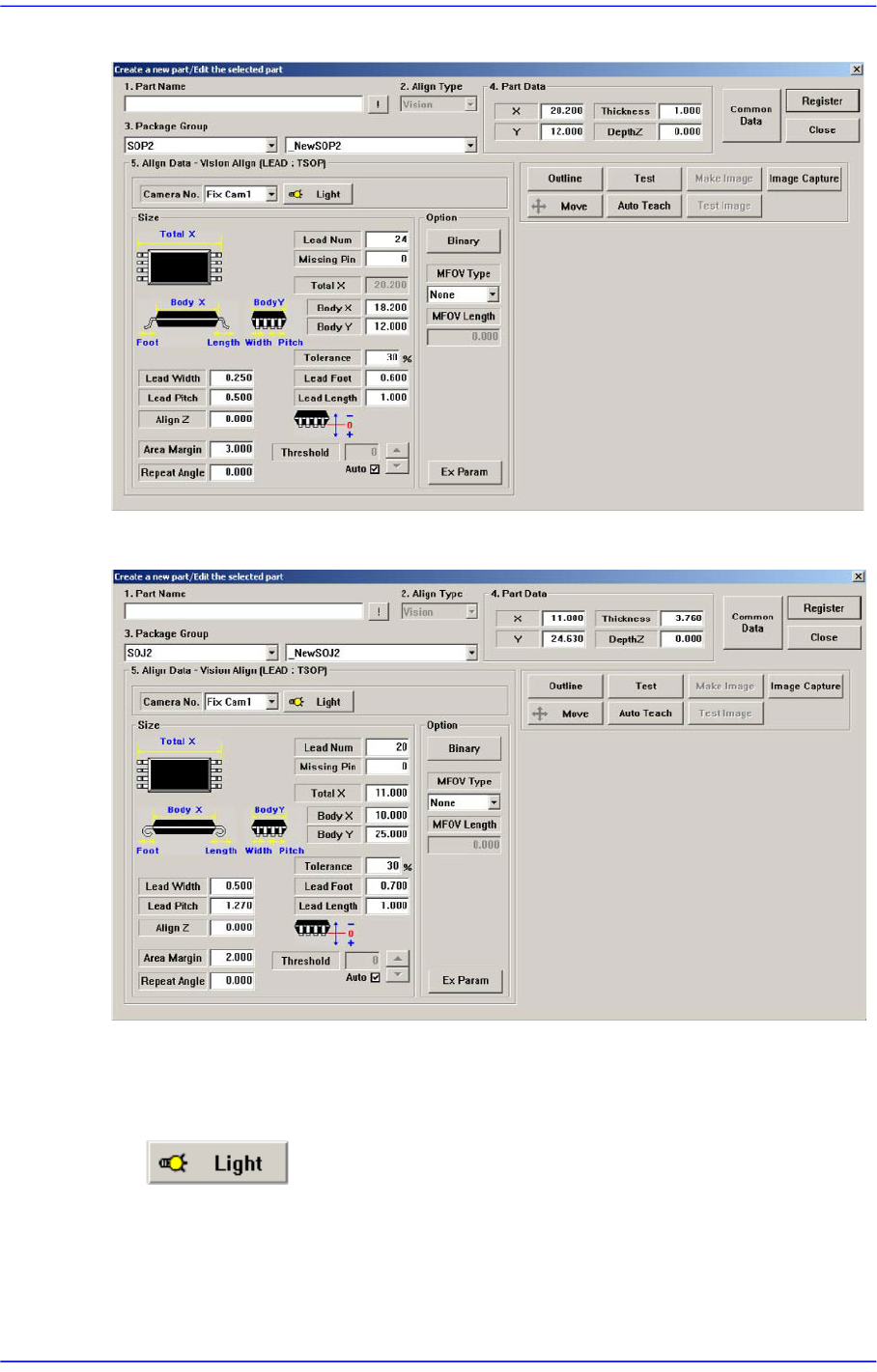
Figure7.20 “Package Group =SOP2”dialog box
Figure7.21 “Package Group =SOJ2”dialog box
<Camera No.> combo box
Select the camera to recognize the component. Please refer to “7.1.1 Common Align
Data” for more Information.
button
Select the light for the camera to recognize the component. Please refer to“7.1.1
Common Align Data” for more Information.
<Size> group