DECAN_S2_Admin(Eng_Ver4.5).pdf - 第228页
7-63 Part Registration Figure7.24 “Package Group =User IC” dialog box <Camera No.> combo box Select the camera to r ecognize the component. Please refer to “7. 1 .1 common Al ign Data” for more inf ormation. &l…
7-62
Advanced Chip Shooter DECAN S2 Administrator’s Guide
<Image Capture> button
Helps to specify the optimum lighting value. The lighting is gradually changed
automatically and the images are saved. The user can check the best image and
identify the optimum lighting value. Please refer to“7.1.1 Common Align Data” for
more Information.
<Auto Teach> button
Automatically finds out the component align data. Please refer to“7.1.1 Common
Align Data” for more Information.
7.1.3.3. PLCC component data setting
Set the align data for PLCC components. Please refer to “7.1.3.5 QFP component data
setting” for more Information.
7.1.4. User IC component data setting
Set align data for User IC components. First, the basic concept behind User IC component
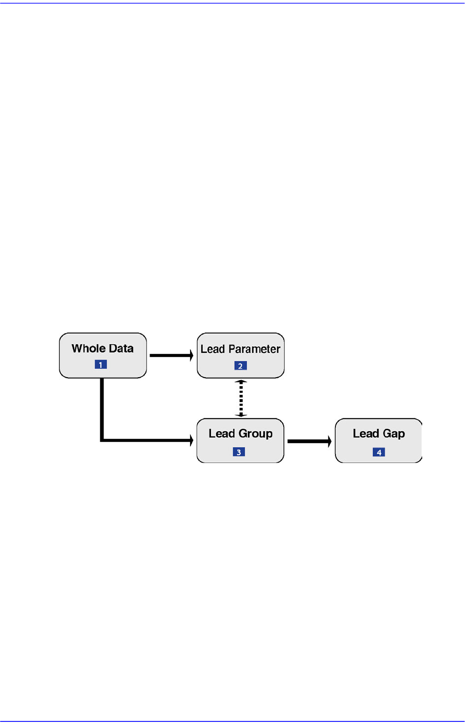
data setting is explained. Please refer to the next figure.
Figure7.23 The basic concept of User IC component data setting
1: Register overall information on the component
2: Data that have lead information on lead forms
3: Data that specify the position where the lead are converged
4: Information on the position of empty in the lead group
User IC component data has one whole data.
User IC component data has up to 16 lead groups.
User IC component data has equal or fewer lead parameters than the lead groups (up to
8).
Each lead group must specify 1 corresponding lead parameter.
Each lead group has up to 4 lead gaps.
7-63
Part Registration
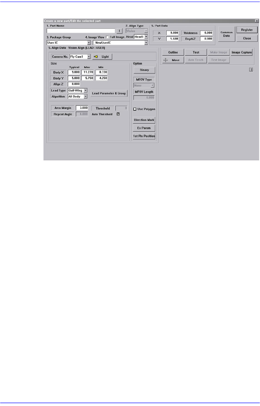
Figure7.24 “Package Group =User IC” dialog box
<Camera No.> combo box
Select the camera to recognize the component. Please refer to “7.1.1 common Align
Data” for more information.
<Size> group
Set the align size.
<Body X Typical> edit box
Set the size of component body in X direction.
<Body X Max> edit box
Set the maximum size of component body in X direction.
<Body X Min> edit box
Set the minimum size of component body in X direction.
<Body Y Typical> edit box
Set the size of component body in Y direction.
<Body Y Max> edit box
Set the maximum size of component body in Y direction.
<Body Y Min> edit box
Set the minimum size of component body in Y direction.
<Lead Type> combo box
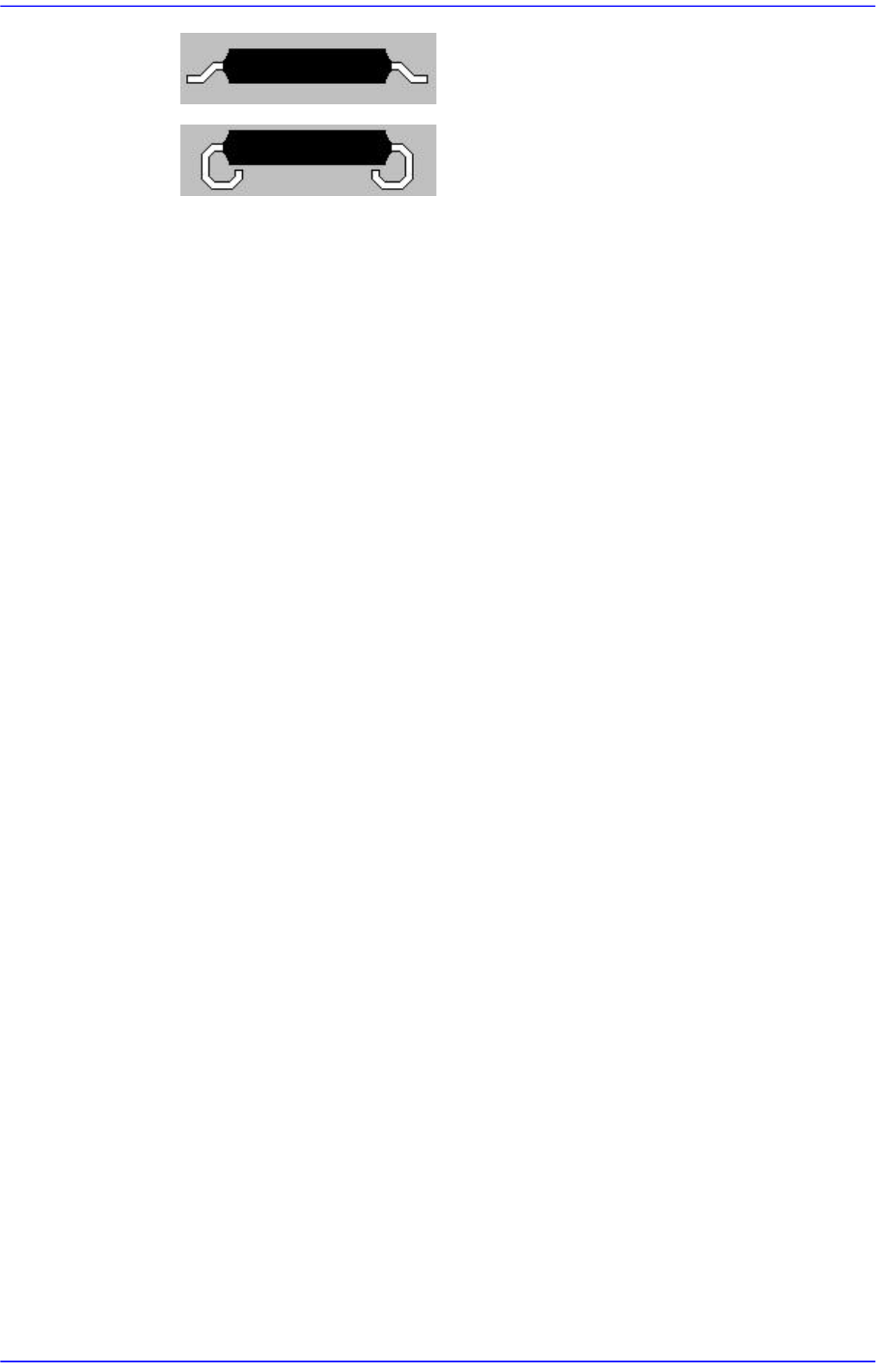
Select the lead type. Available lead types are as follows.
7-64
Advanced Chip Shooter DECAN S2 Administrator’s Guide
Gull-Wing: Leads protrude outward as QFP.
J-Lead: Leads roll inward as PLCC.
<Algorithm> combo box
Select the algorithm to recognize the component. Available algorithms are as
follows.
Black Body
Used in case only lead is displayed brightly on the screen since the color of the
component body is black.
All Body
Used in case lead and body are displayed brightly on the screen since the color
of the component body is bright.
Odd with No Lead
Used for odd shaped parts for which recognition accuracy is not important. Its
recognition algorithm is similar to that of the trimmer.
Odd with Lead
Used for odd shaped parts with leads.
<Lead Parameter & Group> button
Set the lead parameter and lead group.
Please refer to“7.1.1 common Align Data”.
<Option> group
Set the align option data.For other setups, please refer to“7.1.1 common Align Data”.
<Use Polygon> check box
In the case of the part whose recognition precision is not significantly important,
this is used to recognize the part automatically using the Auto Teach function.
Adjust the Threshold and Ex Parameter to suit the characteristics of the
corresponding part so that it can be recognized automatically.
Selecting the <Use Polygon> check box will disable the <Lead Parameter &
Group> button and <MFOV Type> combo box. This enables the <Auto Teach>
button.
At this time, in the <Body X> and <Body Y> edit box of the <Size> group, set the
size of the area in which the polygon is to be searched.
The area in which the polygon is to be searched can be set up by adding the value
entered in the <Area Margin> edit box to the value set by the <Size> group.