DECAN_S2_Admin(Eng_Ver4.5).pdf - 第241页
7-76 Advanced Chip Shooter DECAN S2 Admi nistra t or’s Guide Placement point teaching Select the Reference of the c orr esponding part in the Step dialog box an d click the <Move> button to move the fiducial ca…
7-75
Part Registration
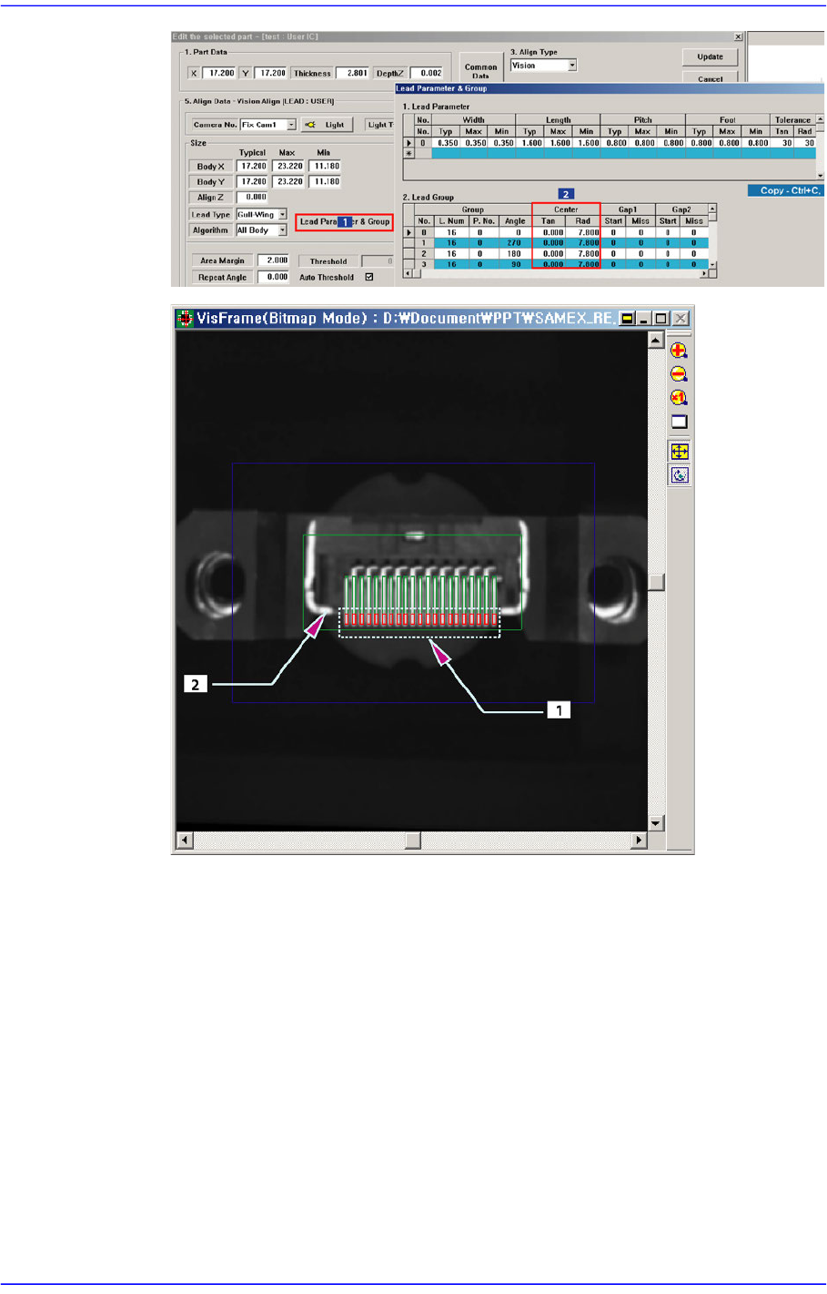
1: Lead End
2: Bright Area
7-76
Advanced Chip Shooter DECAN S2 Administrator’s Guide
Placement point teaching
Select the Reference of the corresponding part in the Step dialog box and click the
<Move> button to move the fiducial camera to the corresponding position.
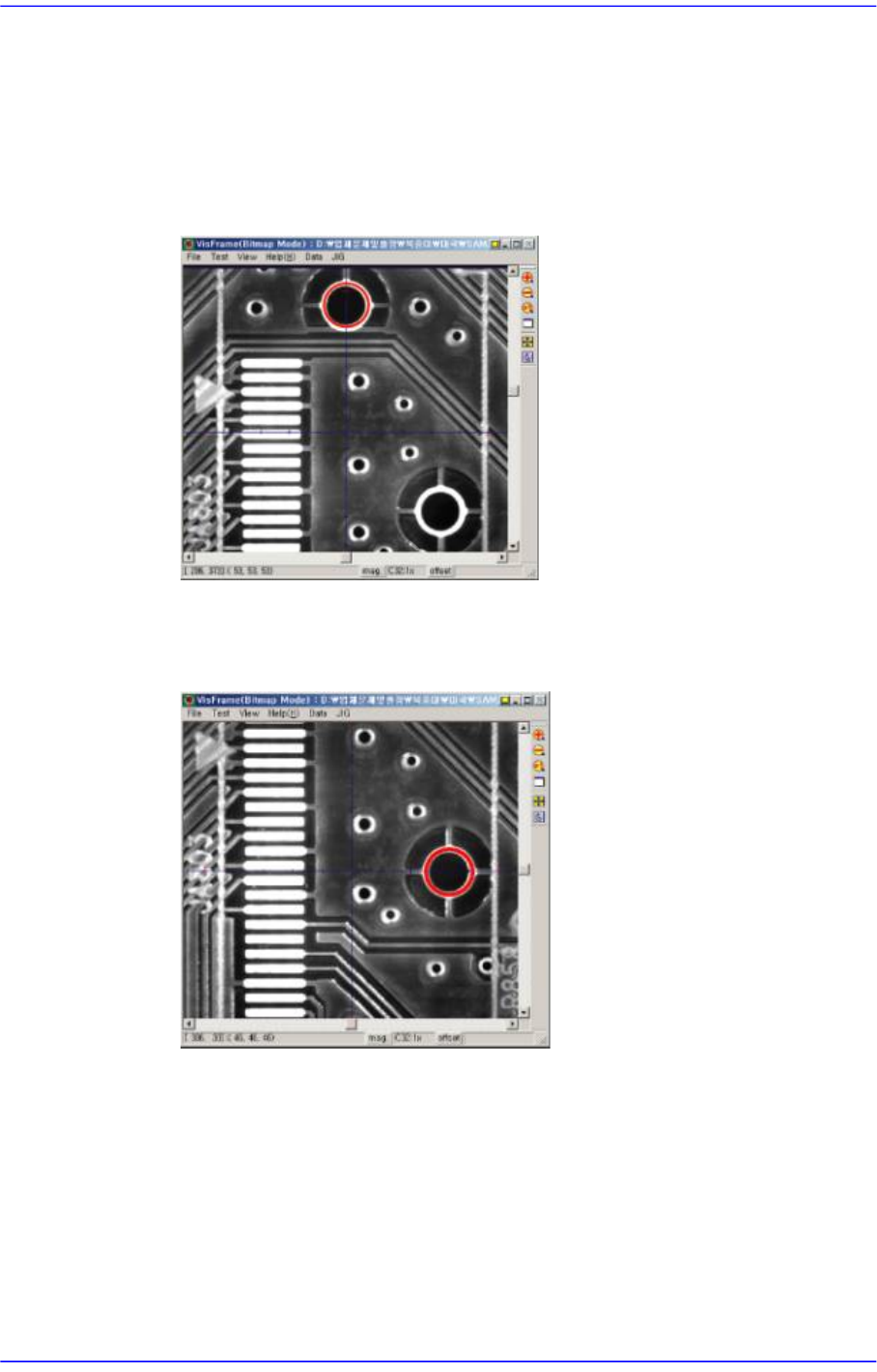
Since the inserting holes for the corresponding part on the PCB do not appear on
the SMVision window, determine the X coordinate of the placement point based
on the center of the upper inserting hole as shown in the following figure.
Move the fiducial camera in the Y axis direction using a jog function and set the
center of the inserting hole to the Y coordinate of the placement point as shown in
the following figure.
7-77
Part Registration
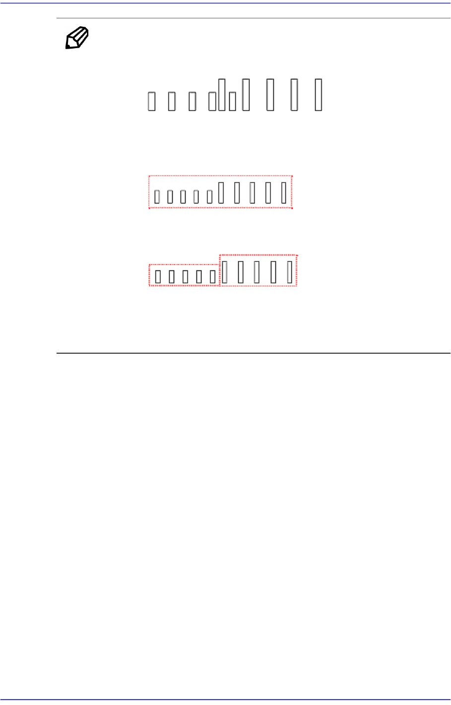
Memo Restrictions
Adjacent lead groups cannot overlap.
Invalid. Because the two lead group are overlapped.
One lead group uses one lead parameter. In other words, a lead
group should only contain leads of the same type.
This lead group cannot be registered as single lead group because
the lead parameters are different.
These lead groups are registered as separate lead group becasue
the lead parameters are different
Leads groups are placed only at right angle directions
7.1.5. Hemt component data setting
Set the align data for Hemt components. Please refer to“7.1.4 User IC component data
setting”.
7.1.6. Connector component data setting
Set the align data for Connector components.
Please refer to “7.1.4 User IC component data setting”.
7.1.7. BGA component data setting
Set the align data for BGA components.