DECAN_S2_Admin(Eng_Ver4.5).pdf - 第25页
Advanced Chip Shooter DECAN S2 Admi nistra t or’s Guide x Specifications of Machine Applicable component sizes Vision recognition system The sizes of components applicable to this machine are prescribed in the following …
Preface
ix
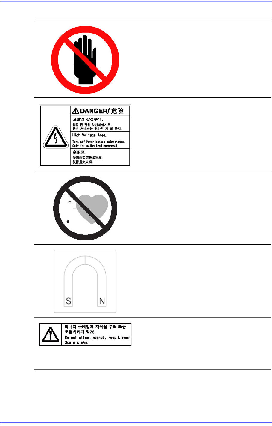
Do not touch the head assembly.
Be careful of electric shock.
Turn off the main switch before performing
maintenance since fatal personnel injury
may occur. Be careful of the residual
current.
Users of artificial cardiac pacemakers
must not approach the machine
If a failure occurs to an artificial cardiac
pacemaker due to the magnetic force of
linear motor inside the cover, the user may
be injured
or die. T
herefore, do not
approach the machine.
Danger of injury due to magnetic force.
If a metallic material or ornament sticks to
the machine due to the magnetic force of
linear motor inside the cover, a person may
be injured. Therefore, exercise caution.
Do not attach a magnet to the linear
scale.
Keep the linear scale clean by preventing
it from being contaminated by foreign
materials.
Advanced Chip Shooter DECAN S2 Administrator’s Guide
x
Specifications of Machine
Applicable component sizes
Vision recognition system
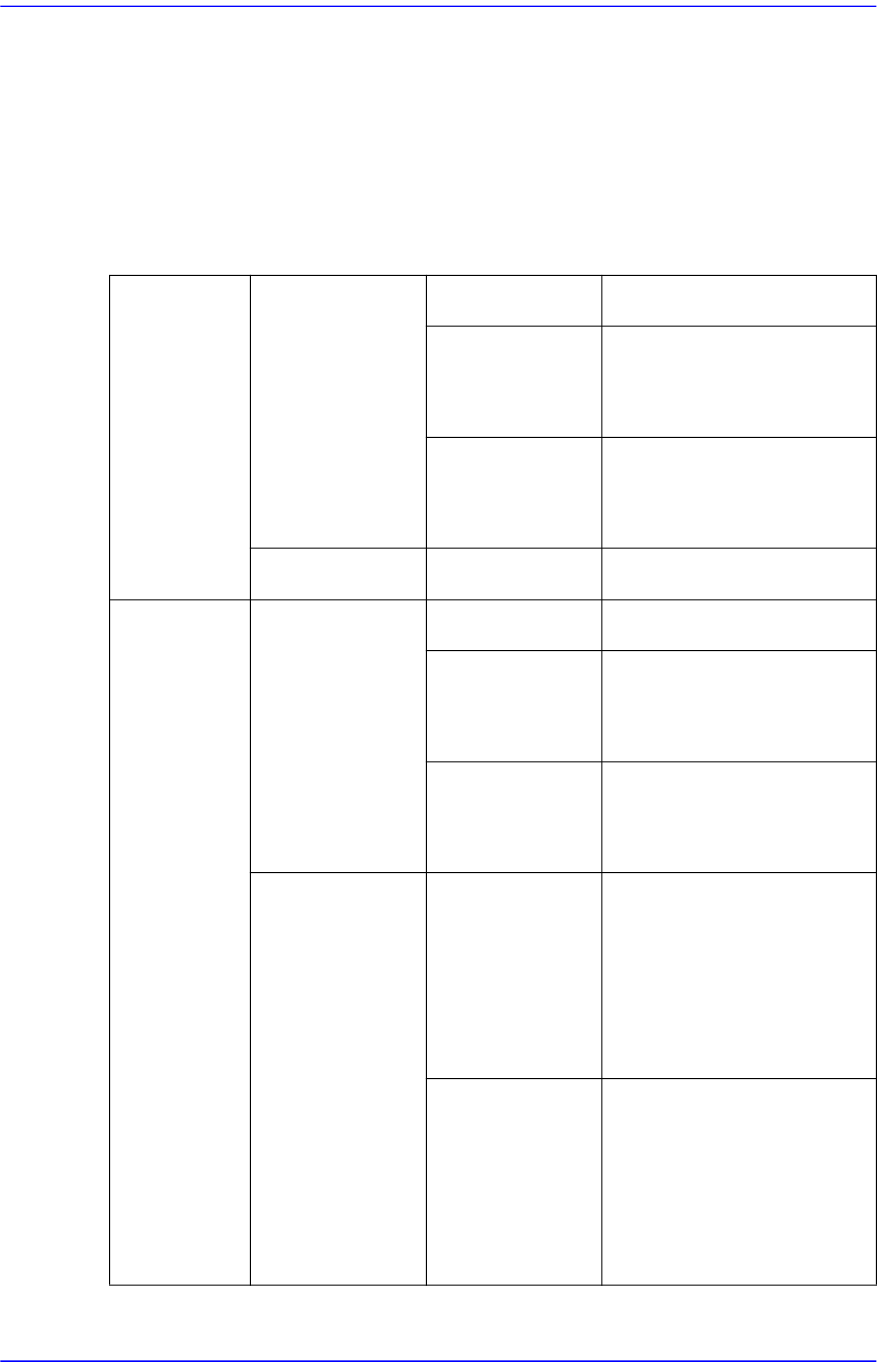
The sizes of components applicable to this machine are prescribed in the following table,
and is applicable to general components usage as well.
Tablei.1Configuration of the Head and Vision Recognition System
Hs Head
Flying vision
MEGA FOV 24
mm
Chips
0402 ~ □16 mm
IC, Connector
Less than □16 mm
Greater than Lead Pitch :
0.4 mm
BGA, CSP
Less than □16 mm
Greater than Ball Pitch : 0.4
mm
Maximum height
Flying vision 12 mm
FS Head
Flying vision
MEGA FOV 24
mm (Front /
Rear)
Chip 0402 ~□ 16 mm
IC, Connector
Less than □16 mm
Greater than Lead Pitch :
0.4 mm
BGA, CSP
Less than □16 mm
Greater than Ball Pitch : 0.4
mm
Upward vision
MEGA
FOV 35
mm (Rear)
IC, Connector
Less than □16 mm
Greater than Lead Pitch :
0.3 mm
Less than □32 mm
Greater than Lead Pitch :
0.4 mm
BGA, CSP
Less than □16 mm
Greater than Ball Pitch : 0.4
mm
Less than □32 mm
Greater than Ball Pitch : 0.5
mm
Preface
xi
The placement Speed
The following data concerns the speed of placement for each part. The actual cycle time
can vary depending on the size of PCB, frequency of the nozzle replacement, etc.
The pick and place cycle time
Tablei.2The pick and place speed
Memo In actual placement, the conditions that determine the cycle time may
vary depending on many factors such as the type of components, size
of PCB, placement position, etc. For more detailed information,
please contact our business department or the local agent.
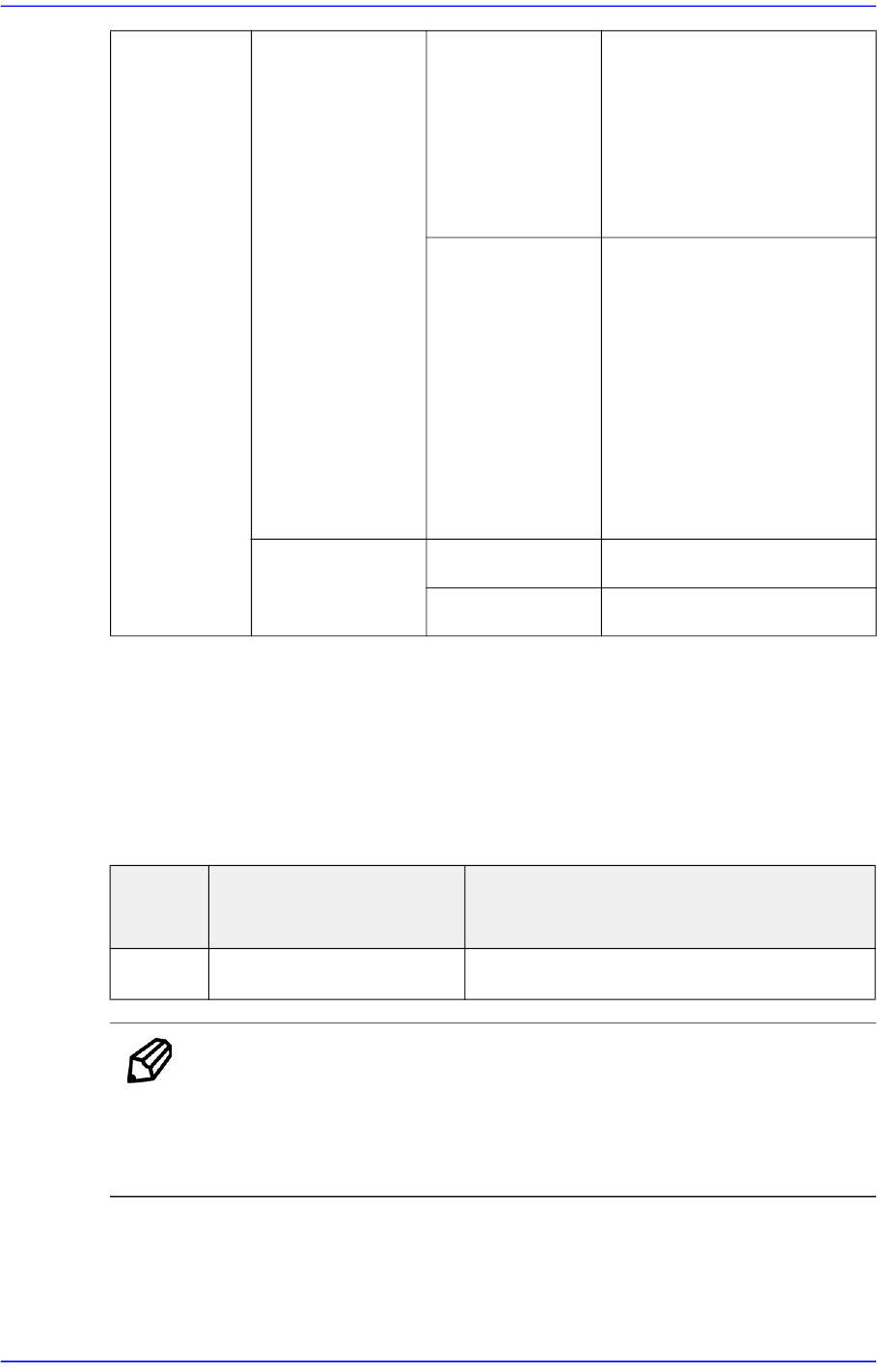
FS Head
Upward vision
MEGA FOV 45
mm (Rear)
IC, Connector
Less than □32 mm
Greater than Lead Pitch :
0.4 mm
Less than □42 mm
Greater than Lead Pitch :
0.5 mm
BGA, CSP
Less than □16 mm
Greater than Ball Pitch : 0.4
mm
Less than □32 mm
Greater than Ball Pitch : 0.5
mm
Less than □42 mm
Greater than Ball Pitch : 1.0
mm
Maximum Height
Flying vision 10 mm
Upward vision 15 mm
Classifi
cation
Speed Remarks
Chip
92,000 CPH (1608)
Simultaneous Pickup Standard Fly Vision