DECAN_S2_Admin(Eng_Ver4.5).pdf - 第251页
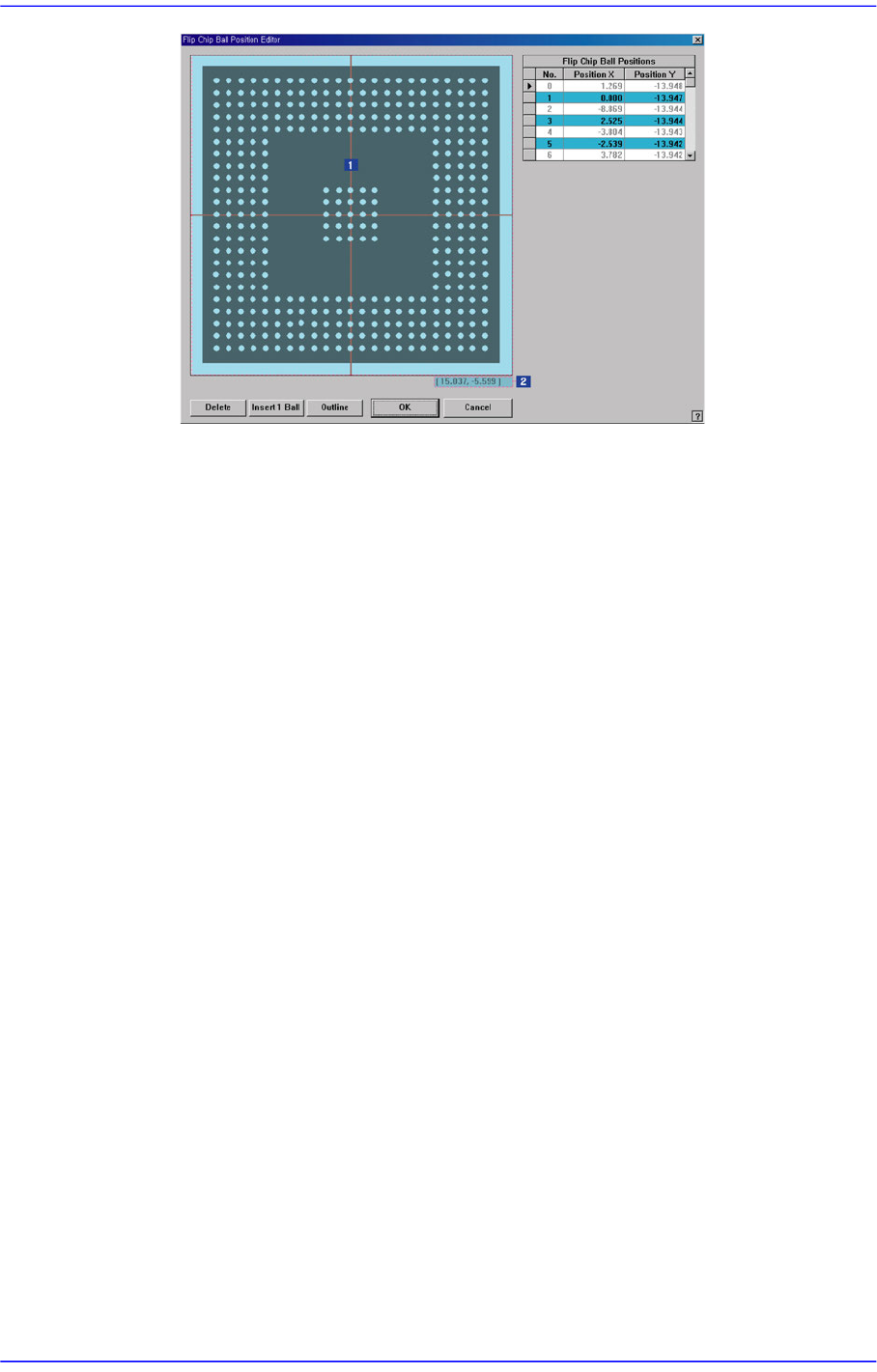
7-86 Advanced Chip Shooter DECAN S2 Admi nistra t or’s Guide 1: Grap hics A rea 2: Pos it ion Display <Gr aphi cs A rea> group Displays currently registered balls. Followin g works can be done in the graphic area…

7-85
Part Registration
7.1.8. FLIP CHIP component data setting
Set the align data for Flip Chip components.
Figure7.31 “Package Group =Flip Chip” dialog box
<Camera No.> combo box
Select the camera to recognize the component. Please refer to“7.1.1 common Align
Data” for more information.
button
Select the camera to recognize the component. Please refer to“7.1.1 common Align
Data” for more information.
<Size> group
Set the align size. Please refer to “7.1.7 BGA component data setting“ of <Size>
group for more information.
<Option> group
Set the align option data.
<Edit Balls> button
Edits the position of each ball.
7-86
Advanced Chip Shooter DECAN S2 Administrator’s Guide
1: Graphics Area
2: Position Display
<Graphics Area> group
Displays currently registered balls. Following works can be done in the
graphic area.
Left Mouse Button Double Click
Creates a new ball where there is mouse cursor.
Ball Selection
Removing the area after generating it while pressing the mouse left button
will select the balls in the selected area.
Pressing the Delete Button will delete the selected balls.
<Position Display>
It is at the right bottom of the graphics area. It displays the position of the
mouse cursor. (Unit: mm)
<Flip Chip Ball Positions> group
Displays the position of the ball. It can be corrected directly.
<No.>
Displays the serial number of the created balls.
<Position X>
Displays the position of the ball in the flip chip body in the X direction.
(Unit: mm)
<Position Y>
Displays the position of the ball in the flip chip body in the Y direction.
(Unit: mm)
7-87
Part Registration
<Delete> button
Deletes the ball selected in the graphic area or the ball selected in the grid.
<Insert 1 Ball> button
Adds a new ball. The initial position of the newly created ball is (0, 0).
<OK> button
Save the edited contents and closes the dialog box.
<Cancel> button
Closes the dialog box without saving the edited contents.
Please refer to “7.1.1 common Align Data” for more information.
<EX Param> button
Displays the dialog box that performs detail setup related to the recognition. For
general component, it is not required to perform setup. Please refer to “7.1.1
common Align Data” for more information.
<Move> button
Used for parts recognition test by manually picking up parts. Please refer to“7.1.1
common Align Data” for more information.
<Test> button
Tests the component recognition using the set align data. Please refer to“7.1.1
common Align Data” for more information.
<Image Capture> button
Helps to specify the optimum lighting value. The lighting is gradually changed
automatically and the images are saved. The user can check the best image and
identify the optimum lighting value. Please refer to“7.1.1 common Align Data” for
more information.